Fixture for hole drilling bit

A drill and fixture technology, applied in the field of machining, can solve the problems of increasing the labor intensity of operators, the drop of the drill or milling head, and the safety of use, and achieves a simplified structure, improved service life, and good use stability. Effect

Inactive Publication Date: 2018-02-09
常州山迪智能科技有限公司
View PDF0 Cites 3 Cited by
  • Summary
  • Abstract
  • Description
  • Claims
  • Application Information

AI Technical Summary

Problems solved by technology

[0003] Drilling in the prior art mainly includes a clamping block and a rotating fastening block. Grooves or threads are arranged in the clamping block and are set apart. The rotating fastening block is arranged on the outside of the clamping block. When drilling or milling When the head is installed on the fixture, the clamping block is gradually clamped by rotating the fastening block, and the drill bit or milling head is fixed through the internal groove or thread, which can guarantee the clamping function to a certain extent, but it is used for a long time When rotating the fastening block, it is easy to make the drill bit or milling head fall off from the clamping block, and the use stability is poor, and there are also certain safety problems in use, and the applicability is limited. , the operator needs to manually turn the hand wheel on the tailstock to advance the drill bit, which increases the labor intensity of the operator, and needs to continuously measure the drilling depth, which reduces the processing efficiency and takes a lot of time

Method used


Image

  • Fixture for hole drilling bit
  • Fixture for hole drilling bit

Examples


Embodiment Construction

[0015] The following will clearly and completely describe the technical solutions in the embodiments of the present invention with reference to the accompanying drawings in the embodiments of the present invention. Obviously, the described embodiments are only some, not all, embodiments of the present invention. Based on the embodiments of the present invention, all other embodiments obtained by persons of ordinary skill in the art without making creative efforts belong to the protection scope of the present invention.

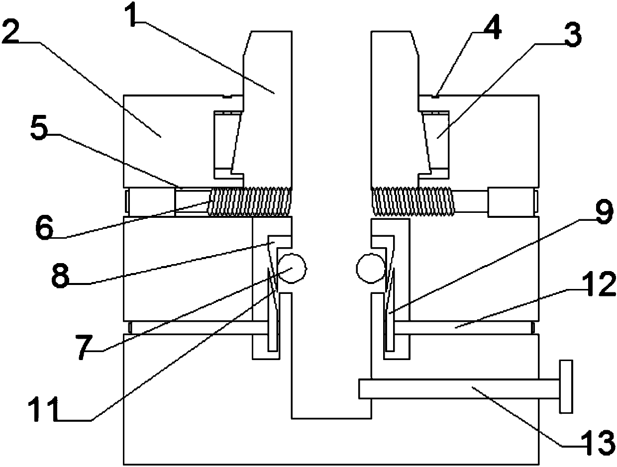
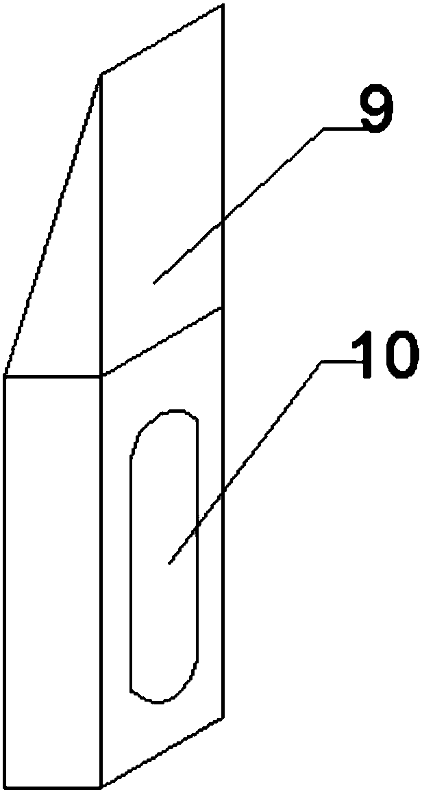
[0016] see Figure 1~2 , a fixture for drilling drills, including a chuck 1, a sleeve 2, a fastening slider 3, a fastening bolt 4, a through groove 5, a rotating rod 6, a fixed steel ball 7, a steel ball push block 8, Movable block 9, screw hole 10, pressure groove 11, fixed screw rod 12 and positioning screw rod 13; The chuck 1 is arranged inside the sleeve 2, the chuck 1 is located at the top of the sleeve 2, and the fastening slide The block 3 is installed...


PUM


Abstract

The invention discloses a fixture for a hole-making drill bit, which includes a chuck, a sleeve, a fastening slide block, a fastening bolt, a through groove, a rotating rod, a fixed steel ball, a steel ball push block, a movable block, and a screw hole , pressure-resisting groove, fixing screw and positioning screw. The beneficial effects of the present invention are: the outer sides of the chuck and the sleeve are coated with a layer of anti-oxidation film, which prevents the surface from being oxidized and rusted, improves the service life of the fixture, and the positioning screw The drill bit placed in the fixture is fixed by rotation, and the drill bit is initially fixed to prevent falling. The fixed screw drives the movable block to move up and down through the rotation, and the fixed drill bit is positioned to prevent the installation from tilting. The rotating rod pushes the chuck to the right The drill bit placed in the fixture is clamped, which simplifies the structure of the fixture and is convenient for the operator to install and disassemble. The fastening slider makes the clamping of the chuck more tight under the action of the fastening bolt, and it can be used for a long time There will be no looseness when using, and the use stability is good.

Description

technical field [0001] The invention relates to a fixture, in particular to a fixture for a hole-making drill bit, and belongs to the technical field of mechanical processing. Background technique [0002] When mechanical parts are drilled, they are generally operated on a drilling machine. The fixture is mainly used on a drilling or milling machine, and it is mainly used to clamp a drill bit or a milling head. [0003] Drilling in the prior art mainly includes a clamping block and a rotating fastening block. Grooves or threads are arranged in the clamping block and are set apart. The rotating fastening block is arranged on the outside of the clamping block. When drilling or milling When the head is installed on the fixture, the clamping block is gradually clamped by rotating the fastening block, and the drill bit or milling head is fixed through the internal groove or thread, which can guarantee the clamping function to a certain extent, but it is used for a long time When...

Claims


Application Information

Patent Timeline
Patent Type & Authority Applications(China)
IPC IPC(8): B23Q3/00
CPCB23Q3/00
Inventor 明伟伟沈彬
Owner 常州山迪智能科技有限公司
Why Eureka
Try Eureka