Track travelling device

A crawler walking device and crawler technology, which are applied to tracked vehicles, transportation and packaging, motor vehicles, etc., can solve the problems of weakening impact force, high positioning requirements, and impracticality, and achieve stable and reliable work, good desilting effect, and structural simple effect

Pending Publication Date: 2018-02-09
HUNAN AGRICULTURAL UNIV
View PDF0 Cites 4 Cited by
  • Summary
  • Abstract
  • Description
  • Claims
  • Application Information

AI Technical Summary

Problems solved by technology

[0004] 1. It is simple, practical and reliable to use external forces such as gas and liquid to perform impact desilting, but in the application process, there are disadvantages such as high positioning requirements, sufficient impact pressure requirements, and high energy consumption, and it is suitable for underwater (in liquid) working environments. It is said that due to the great water resistance, the effective impact force will be greatly weakened, so there are big problems in engineering applications, and only theoretical suggestions have been put forward at present.
[0005] 2. Using the method of vibration to remove mud not only requires a large impact force, but also requires a large amplitude to adhere to the track, which is contradictory to the tensioning of the work vehicle and the track itself, and is not practical, and The adhesion force of the soft bottom of the seabed and other geology is very strong, and ordinary vibration cannot make the adhered sea mud detach at all.
[0006] 3. Surface engineering is used to remove mud by treating the contact surface or changing its shape, such as using a hard brush, which can improve the degree of adhesion and reduce the adhesion force to a certain extent, but this change is very weak , it has almost no effect on the sea mud and other substrates with strong adhesion, and the crawler running mechanism of the work vehicle is very simple and optimized, and it is not suitable for changing the shape structure to a large extent, so this method is not applicable

Method used


Image

  • Track travelling device
  • Track travelling device
  • Track travelling device

Examples


Embodiment Construction

[0026] The present invention will be described in further detail below in conjunction with the accompanying drawings and specific embodiments.

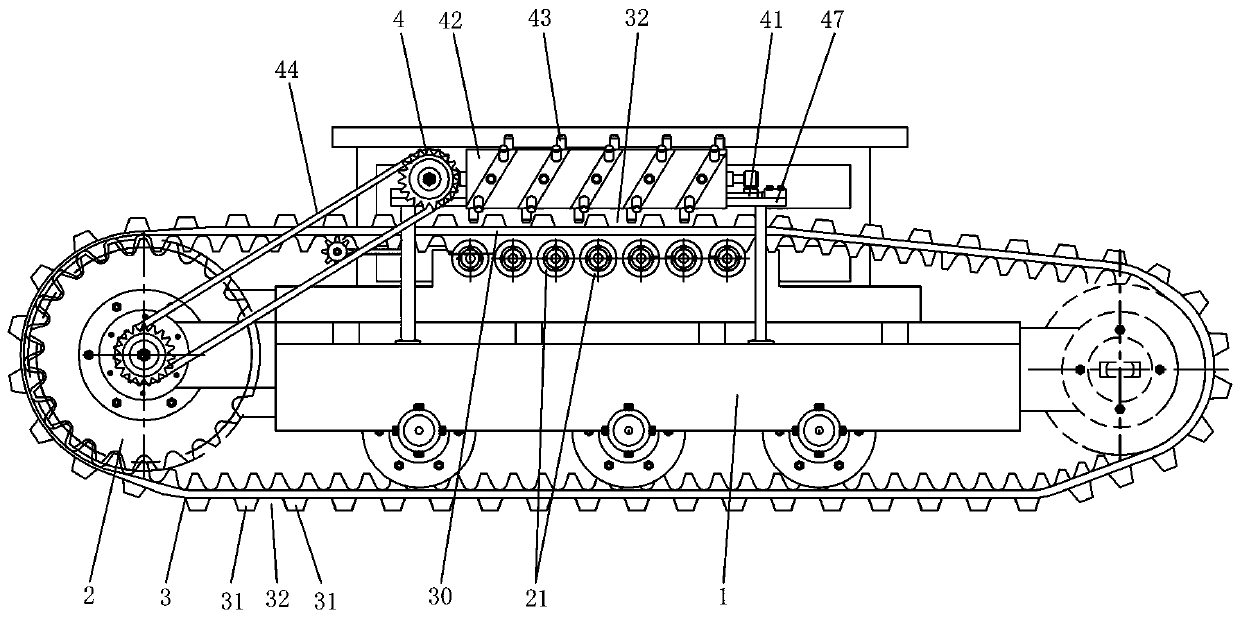
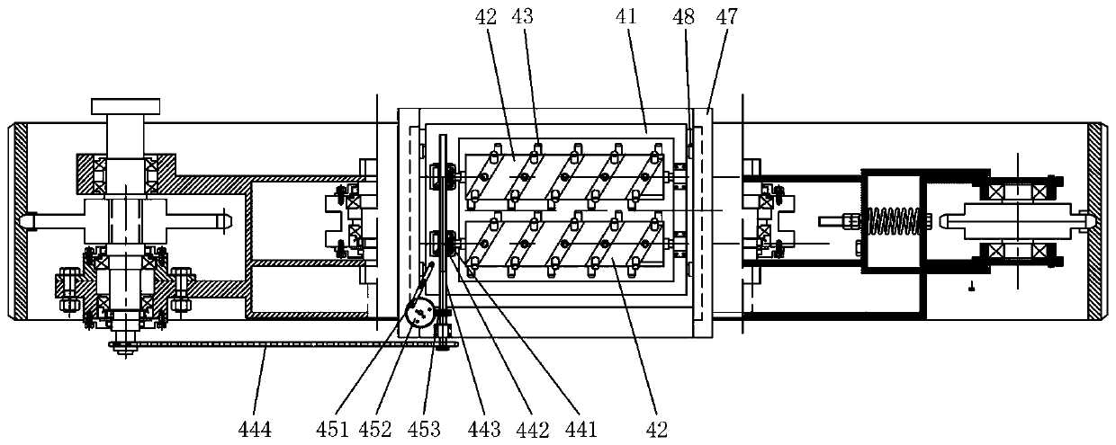
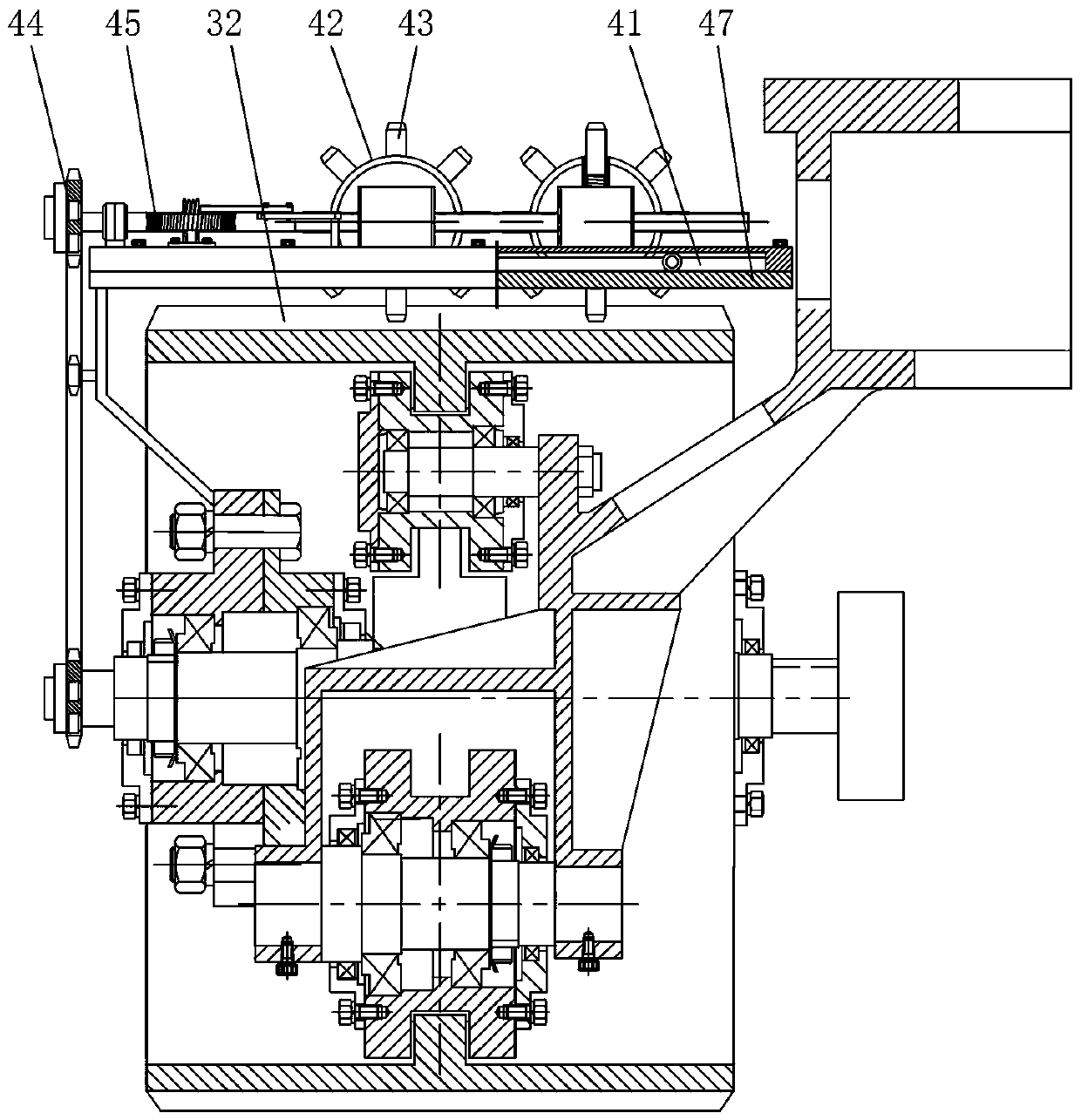
[0027] Such as Figure 1 to Figure 3 As shown, the crawler belt running device of this embodiment includes a bracket 1, a pulley unit 2 installed on the bracket 1, and a walking crawler 3 wound on the pulley unit 2, and the walking crawler 3 has several grouser teeth 31 arranged at intervals. Between the adjacent crawler teeth 31, a tooth groove 32 extending along the width direction of the walking crawler belt 3 is formed. The upper part of the walking crawler belt 3 has a mud removal section 30, and the mud in the tooth groove 32 for removing the mud removal section 30 is installed on the bracket 1 The mud removal device 4 includes a sliding seat 41 that is slid on the support 1 along the width direction of the walking crawler belt 3, more than one rotating roller 42 that is installed on the sliding seat 41 and is located above the ...


PUM


Abstract

Disclosed is a track travelling device. The track travelling device comprises a support, track wheel units mounted on the support and a travelling track wound on the track wheel units; a plurality oftrack teeth are arranged on the travelling track at intervals; tooth grooves extending in the width direction of the travelling track are formed between the adjacent track teeth; a mud removing section is arranged on the upper portion of the travelling track; a mud removing device for removing mud in the tooth grooves of the mud removing section is mounted on the support; the mud removing device comprises a sliding seat slidably arranged on the support in the width direction of the travelling track, more than one rotating roller mounted on the sliding seat and located above the mud removing section, and a rotating driving assembly for driving the rotating rollers to rotate; each rotating roller is provided with a plurality of mud-scraping toothed rods, wherein the multiple mud-scraping toothed rods are spirally arranged around the rotating roller and pass through all the tooth grooves of the mud removing section in sequence along with rotating of the rotating roller; and the mud removing device further comprises a sliding driving assembly for driving the sliding seat to slide. The track travelling device has the advantages of being simple in structure, easy to manufacture, low in cost, good in mud removing effect, low in energy consumption, stable and reliable in working and the like.

Description

technical field [0001] The invention relates to the technical field of crawler walking equipment, in particular to a crawler walking device. Background technique [0002] During the walking process of the crawler walking device, the walking crawler will contact the ground soil to a certain degree of adhesion behavior. If the continuously adhered soil is not removed in time, it will slowly accumulate and be subjected to repeated pressure by continuously revolving around the contact surface between the crawler belt and the substrate. It is reinforced by pressure, so as to gradually fill the gap between the high teeth of the track shoe, and reduce the actual height of the track shoe, which will lead to a decrease in the friction between the walking track and the ground, and the phenomenon of not getting old grip and slipping, which is serious Affect the passing capacity, operation quality and work efficiency of the crawler walking device. Therefore, it is necessary to remove t...

Claims


Application Information

Patent Timeline
IPC IPC(8): B62D55/088
CPCB62D55/0882
Inventor 李军政孙松林蒋蘋谢方平彭才望李旭胡文武
Owner HUNAN AGRICULTURAL UNIV
Why Eureka
Try Eureka