Overflow dam front hydraulic automatic desilting system and construction method

A hydraulic automatic and construction method technology, applied in water conservancy engineering, marine engineering, coastline protection, etc., can solve the problems of poor silt reduction effect, soil erosion, and high cost of siltation, and achieve good silt reduction effect, convenient maintenance, and operation. Maintenance-friendly effect

Pending Publication Date: 2018-06-12
CHANGSHA UNIVERSITY OF SCIENCE AND TECHNOLOGY
View PDF15 Cites 0 Cited by
  • Summary
  • Abstract
  • Description
  • Claims
  • Application Information

AI Technical Summary

Problems solved by technology

The first type of method requires a large modification of the dam body, and the silt reduction effect on the silt and sand in the far area in front of the dam is not good
The second type of method needs to deal with a large amount of dredged mud and sand, which has many links, high cost and easy to cause soil erosion

Method used


Image

  • Overflow dam front hydraulic automatic desilting system and construction method
  • Overflow dam front hydraulic automatic desilting system and construction method
  • Overflow dam front hydraulic automatic desilting system and construction method

Examples


Embodiment Construction

[0024] The technical solutions of the present invention will be further described in detail below in conjunction with the accompanying drawings.

[0025] Example.

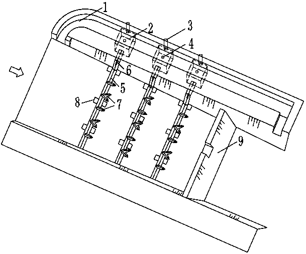
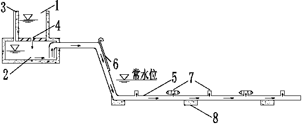
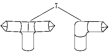
[0026] The invention discloses a hydraulic automatic silt reduction system and a construction method in front of a rolling dam. The silt reduction system includes a bank diversion channel 1 , a sump 2 , a sand washing pipe 5 and a fixed pier 8 . The sump 2 is located at the bottom of the water diversion canal 1, and the vent hole 3 (to balance the pressure of the sump 2 and the outside atmosphere) and the water inlet 4 are arranged on the top of the sump, and the sand washing pipe 5 is connected to the side of the sump. The inlet section of the sand washing pipe 5 is an inverted U-shaped pipe, the flat pressure pipe 6 is arranged on the slope section, and the sand washing nozzle 7 is arranged on the pipe body of the river section fixed by the fixed pier 8 .

[0027] Further, in the diversion canal 1, the head of ...


PUM

PropertyMeasurementUnit
Diameteraaaaaaaaaa
Diameteraaaaaaaaaa

Abstract

The invention discloses an overflow dam front hydraulic automatic desilting system and a construction method. The desilting system comprises a shoreside diversion canal, a water collection groove, a sand flushing pipe and a fixed pier. The water collection groove is located at the bottom of the diversion canal, the groove top is provided with a water inlet hole and a vent hole, and the groove sideis connected with the sand flushing pipe. The inlet section of the sand flushing pipe is an n-shaped pipe, the slope section of the sand flushing pipe is provided with a flat pressing plate, and a river channel section pipe body fixed by the fixed pier is provided with a sand flushing spray head. Water constantly flows into the water collection groove through the diversion canal, the siphon phenomenon is automatically induced when the water level in the groove reaches the top of the n-shaped pipe and then is continuously sprayed from the sand flushing spray head with the large flow speed, local turbulent flow is formed before a dam to prevent sand deposition, sand is driven to flow into a downstream river channel through dam body sand discharge holes. The construction method comprises thefirst step of building the diversion canal, the water collection groove and the fixed pier, the second step of prefabricating components, and the third step of carrying out sectional installation onsite. Jet flow and turbulent flow are automatically formed through the siphon principle to constantly drive sand, and the system has the advantages of being good in desilting effect, convenient to operate and maintain, ecological and environmentally friendly.

Description

technical field [0001] The invention belongs to the technical field of hydraulic sand removal, in particular to a hydraulic automatic silt reduction system and construction method in front of a rolling water dam. Background technique [0002] Rolling dams have been widely used in the comprehensive management of small and medium watersheds in mountainous areas and have achieved good social benefits. However, during the operation of the rolling dam, the flow rate of the water flow is reduced due to the dam body’s retention, and the sediment in the water gradually deposits in front of the dam, which often leads to serious consequences such as extensive siltation in front of the dam, reduction in storage capacity, and weakening or even disappearance of the river’s ecological flow regulation function. [0003] At present, there are two main methods for reducing and dredging silt in front of rolling dams in mountainous areas: first, changing the structural type of rolling dams. T...

Claims


Application Information

Patent Timeline
IPC IPC(8): E02B7/02E02B8/02
CPCE02B7/02E02B8/02
Inventor 秦卫星胡惠仁邓思佳吴依婷晏巍邹定全陈宏
Owner CHANGSHA UNIVERSITY OF SCIENCE AND TECHNOLOGY
Why Eureka
Try Eureka