
A biped robot and its leg shock absorption and energy recovery device

An energy recovery device and biped robot technology, applied in the direction of electromechanical devices, transportation and packaging, control of mechanical energy, etc., can solve the problems of restricting battery life, operation and load capacity, poor stability, easy wrestling and skidding, etc., to achieve extended battery life and The effects of improving workability, improving stability, and reducing energy consumption

Active Publication Date: 2019-09-20
深圳市行者机器人技术有限公司
View PDF7 Cites 0 Cited by
  • Summary
  • Abstract
  • Description
  • Claims
  • Application Information

AI Technical Summary

Problems solved by technology

[0003] However, when the biped robot in the prior art walks on uneven ground, it is easy to wrestle and slip, and the stability is poor.
[0004] Moreover, the legs of biped robots in the prior art mostly adopt a three-joint structure, the foot structure is too large, and the shock is cushioned by the ankle joint, which makes it difficult to control and the cushioning effect is not ideal.
[0005] In addition, due to the real-time driving of the biped robot, the energy consumption is high, which seriously restricts its battery life, operation and load capacity.
[0006] Therefore, prior art still needs to improve and develop

Method used


Image

  • A biped robot and its leg shock absorption and energy recovery device
  • A biped robot and its leg shock absorption and energy recovery device
  • A biped robot and its leg shock absorption and energy recovery device

Examples


Embodiment Construction

[0020] The specific embodiments and examples of the present invention will be described in detail below in conjunction with the accompanying drawings. The described specific embodiments are only used to explain the present invention, and are not intended to limit the specific embodiments of the present invention.

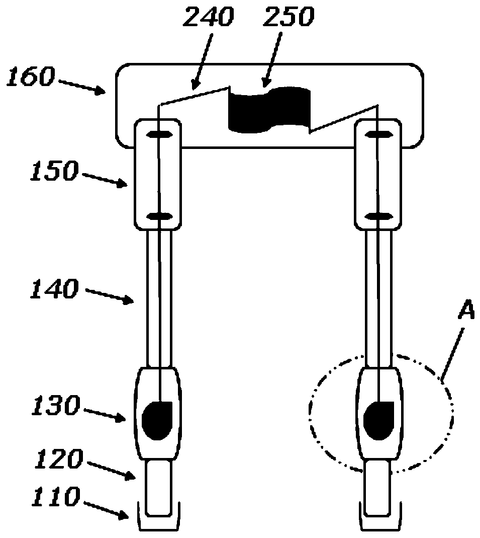
[0021] Such as figure 1 as shown, figure 1 It is a structural schematic diagram of an embodiment of a biped robot leg shock absorption and energy recovery device of the present invention. The leg shock absorption and energy recovery device of a biped robot includes left and right foot components 110, left and right tibia components 120, and left and right knee joint components 130 , left and right femoral components 140, left and right thigh components 150 and hip joint components 160; wherein, the left and right foot components 110 are respectively connected to the lower ends of the left and right tibial components 120, and the left and right knee components 130 ar...


PUM


Abstract

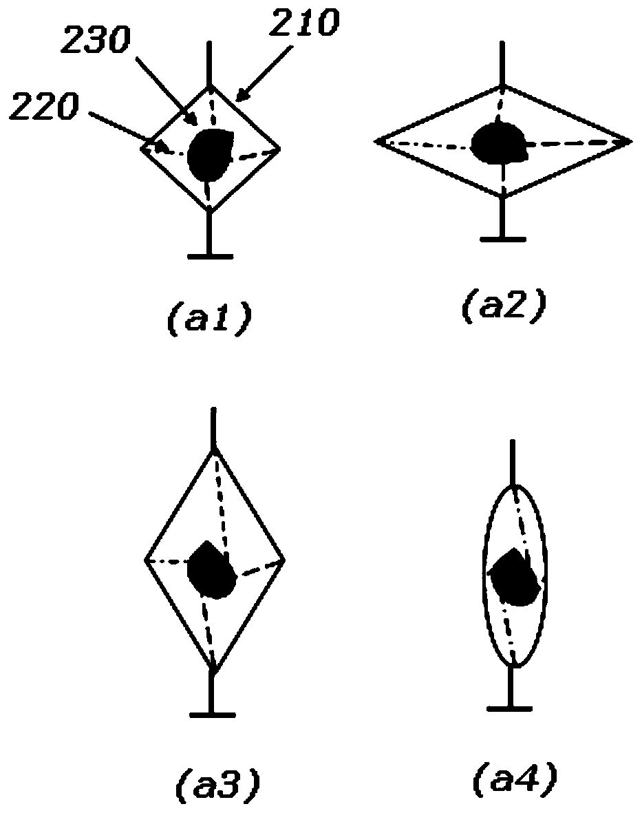
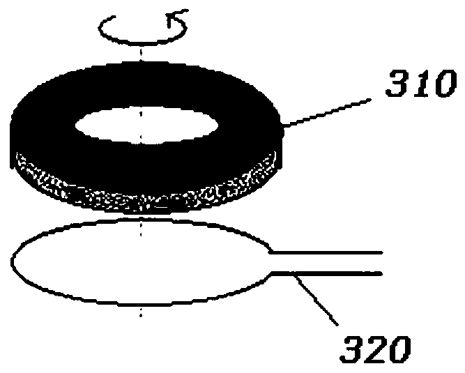
The invention discloses a biped robot and a leg damping and energy recycling device thereof. Four-bar linkage mechanisms are arranged at a left knee-joint assembly and a right knee-joint assembly correspondingly, each four-bar linkage mechanism is internally provided with four pulling lines, a permanent magnet block and a magnetic wire coil, the permanent magnet blocks are located in the magneticwire coils, the inner side ends of each four pulling lines are connected with the corresponding permanent magnet block, the outer side ends of every four pulling lines a are connected with four connecting points of the corresponding four-bar linkage mechanism correspondingly, an electric energy storage device is further arranged in a hip-joint assembly, and the magnetic wire coils are electricallyconnected with the electric energy storage device through connecting lines. Because the four-bar linkage mechanisms are adopted at knee joints and every four pulling lines are utilized to pull the corresponding permanent magnet block to rotate in the corresponding magnetic wire coil to generate electricity, mechanical energy can further be converted to electric energy to be stored while effectiveshock buffering is conducted, so that the stability of the biped robot is improved, energy consumption of the biped robot is reduced, the endurance and operation capabilities of the biped robot are improved, and the biped robot particularly adapts to walking on a complex road surface.

Description

technical field [0001] The invention relates to the field of a biped robot and its leg devices, in particular to a biped robot and its leg shock absorption and energy recovery device. Background technique [0002] At present, the research of robots is an innovative hotspot all over the world, especially the research on biped robots (or humanoid robots) in anthropomorphic form is in full swing. [0003] However, when the biped robot in the prior art walks on uneven ground, it is easy to wrestle and slip, and has poor stability. [0004] Moreover, the legs of biped robots in the prior art mostly adopt a three-joint structure, the foot structure is too large, and the shock is cushioned by the ankle joint, so the control is difficult and the cushioning effect is not ideal. [0005] In addition, due to the real-time driving of biped robots, the energy consumption is high, which seriously restricts its battery life, operation and load capacity. [0006] Therefore, the prior art ...

Claims


Application Information

Patent Timeline
Patent Type & Authority Patents(China)
IPC IPC(8): B62D57/032H02K7/18
Inventor 王成刚
Owner 深圳市行者机器人技术有限公司
Learn More