Combined multi-rotor unmanned aerial vehicle

A multi-rotor unmanned aerial vehicle, combined technology, applied in the field of aircraft, can solve the problems of increased storage and maintenance costs, long development cycle and high cost

Pending Publication Date: 2018-02-09
珠海天晴航空航天科技有限公司
View PDF0 Cites 4 Cited by
  • Summary
  • Abstract
  • Description
  • Claims
  • Application Information

AI Technical Summary

Problems solved by technology

Therefore, the development cycle of traditional UAVs is long and the cost is high, and at the same time, the cost of storage and maintenance in the later period is continuously increasing.

Method used


Image

  • Combined multi-rotor unmanned aerial vehicle
  • Combined multi-rotor unmanned aerial vehicle
  • Combined multi-rotor unmanned aerial vehicle

Examples


Embodiment Construction

[0022] The concept, specific structure and technical effects of the present invention will be clearly and completely described below with reference to the embodiments and accompanying drawings, so as to fully understand the purpose, characteristics and effects of the present invention. Obviously, the described embodiments are only a part of the embodiments of the present invention, rather than all the embodiments. Based on the embodiments of the present invention, other embodiments obtained by those skilled in the art without creative efforts are all within the scope of The scope of protection of the present invention.

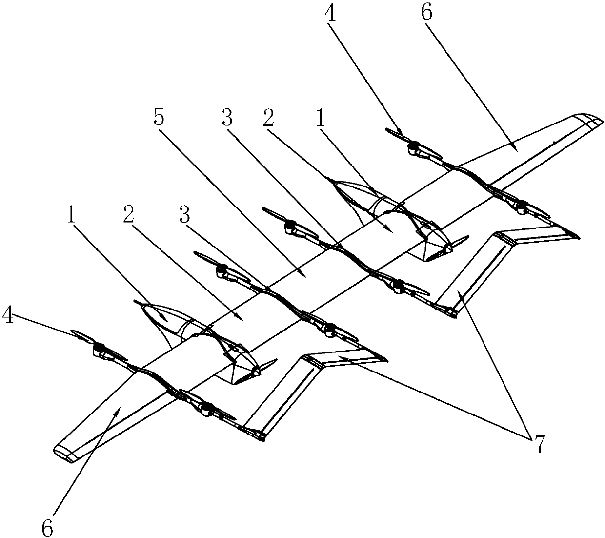
[0023] refer to Figure 1 to Figure 7 , a combined multi-rotor UAV, comprising at least two side-by-side fuselages 1, the fuselage 1 is provided with a central wing 2, both ends of the central wing 2 are provided with tail braces 3, the tail braces The front end and / or the rear end of the rod 3 is provided with a rotary wing 4 , preferably, a rotary wing 4 is...


PUM


Abstract

The invention discloses a combined multi-rotor unmanned aerial vehicle (UAV) which comprises at least two fuselages arranged side by side, wherein the fuselages are provided with central wings; both ends of each central wing are provided with tail booms; rotors are arranged at the front and / or rear ends of the tail booms; the tail booms between every two adjacent fuselages are connected by a corresponding connecting wing; and the tail booms arranged at the outer sides of the fuselages arranged at the side ends are connected with outer wings. The combined multi-rotor UAV connects the fuselagesarranged side by side by the connecting wings to form the UAV in a multi-rotor mode and form a modular design. The combined multi-rotor UAV can select a corresponding number of the fuselages for combination according to different requirements. The combined multi-rotor UAV can also be used for modular disassembly. The independent UAV corresponding to the number of the fuselages can be assembled only by adding a plurality of general wing parts. The combined multi-rotor UAV is suitable for different requirements of use, mission modes or load weight by virtue of assembly and disassembly.

Description

technical field [0001] The invention relates to the technical field of aircraft, in particular to a combined multi-rotor unmanned aerial vehicle. Background technique [0002] At present, among the currently developed UAVs, most of each model is in a fixed mission mode and bears a fixed load weight. Moreover, during the development, taking into account the cost, schedule, reliability and other factors of the UAV, and trying to achieve the best effect, the UAV development generally meets the principle of minimum use requirements. When the usage requirements, mission mode or load weight change, different models need to be designed to achieve this, and each model needs to complete the corresponding research and development process. Therefore, the development cycle of traditional UAVs is long and the cost is high, and at the same time, the cost of storage and maintenance in the later period continues to increase. SUMMARY OF THE INVENTION [0003] In view of the above problem...

Claims


Application Information

Patent Timeline
IPC IPC(8): B64C1/06B64C27/08
CPCB64C1/069B64C27/08B64C2001/0045B64U10/10
Inventor 贺军房佳琦曲长征霍俭娃岳静雯王志刚孙英鑫杨鹏
Owner 珠海天晴航空航天科技有限公司
Why Eureka
Try Eureka