

Intermediate tank truck of continuous casting machine
A technology for tundish trucks and continuous casting machines, which is applied to casting equipment, casting molten material containers, lifting devices, etc. It can solve the problems of out-of-synchronization of the enlarged hydraulic control system, easy deformation of the tundish size, and increased construction costs. The effect of correcting and adjusting problems, improving bearing capacity, and reducing equipment failure rate
- Summary
- Abstract
- Description
- Claims
- Application Information
AI Technical Summary
Problems solved by technology
Method used
Image

Examples
Embodiment Construction
[0025] The present invention will be described in detail below in conjunction with the accompanying drawings and embodiments.
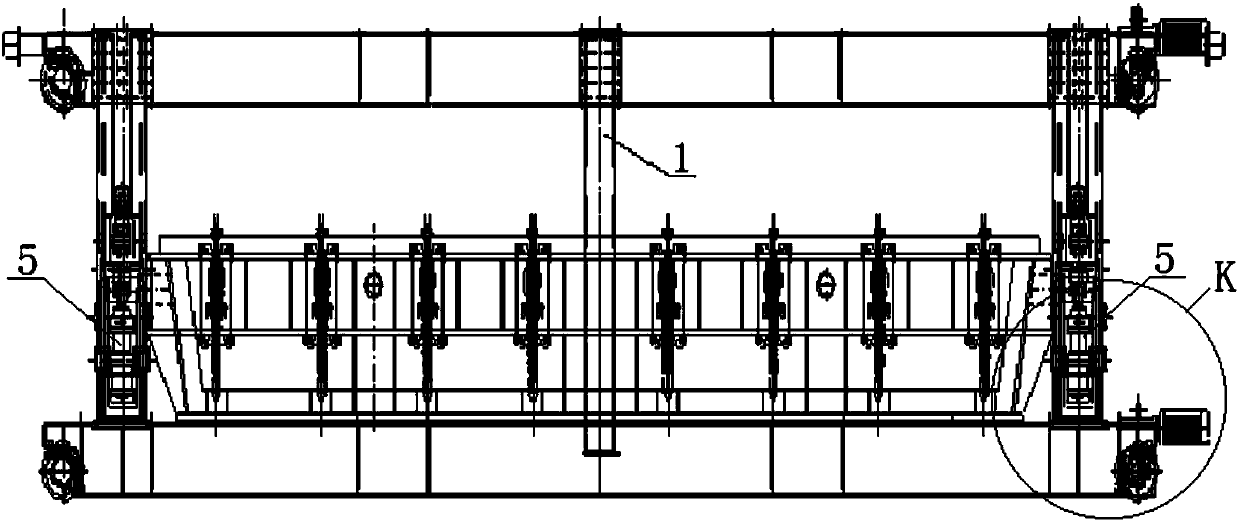
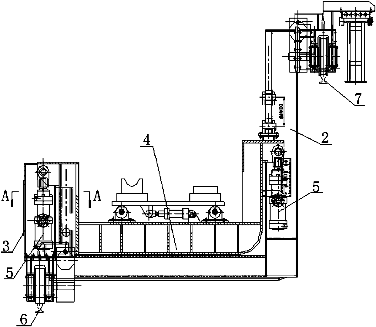
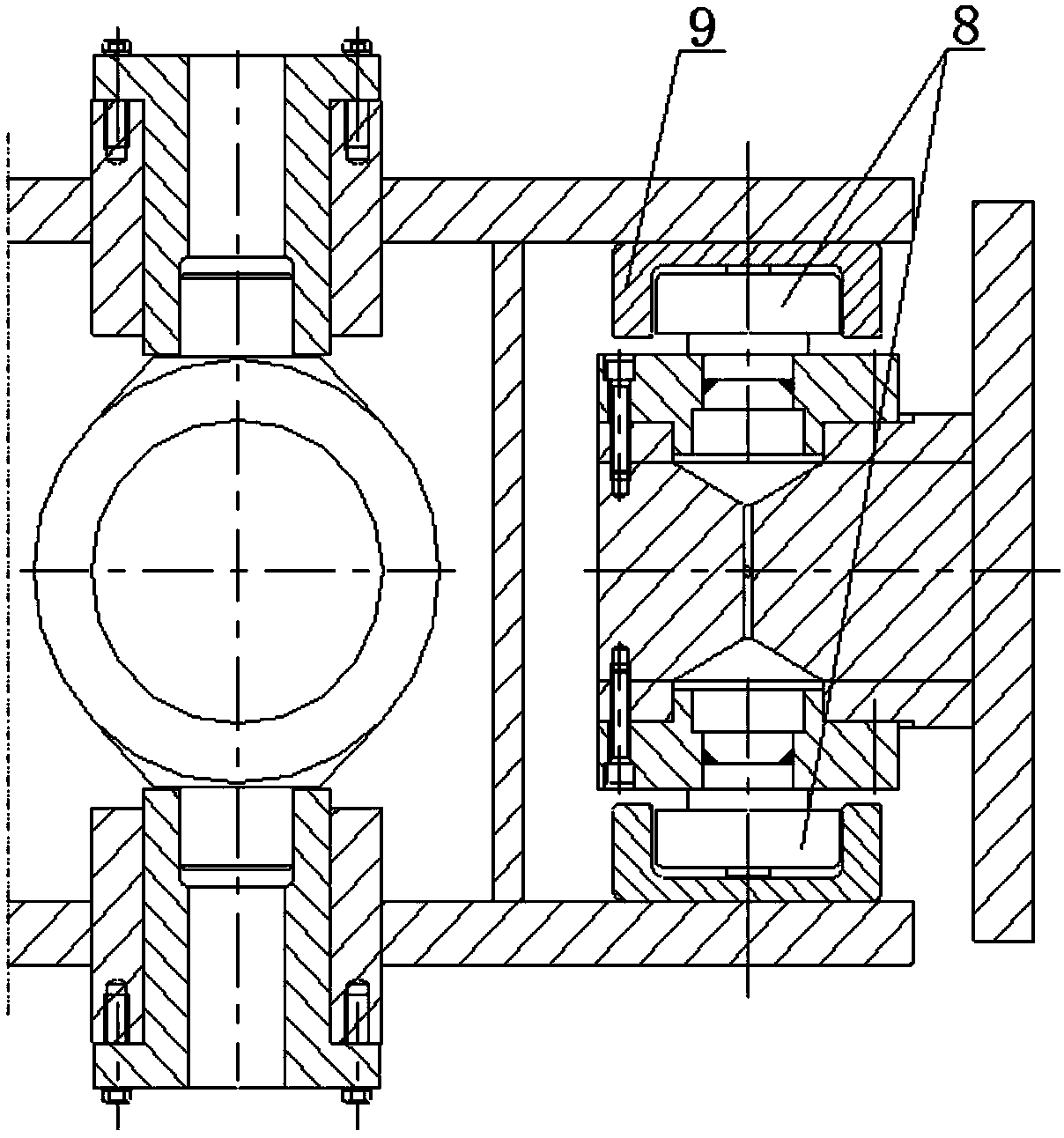
[0026] refer to Figure 1 ~ Figure 4 As shown, the tundish car of the continuous casting machine in an embodiment provided by the present invention includes a lifting mechanism 4, a low leg 3 and a high leg 2, the lifting mechanism 4 includes a bracket and four lifting cylinders 5, and the four lifting cylinders 5 are distributed Around the bracket, the low leg 3 and the high leg 2 are respectively arranged on both sides of the bracket, and the bracket is respectively connected with the low leg 3 and the high leg 2 through the lifting cylinder 5, and the low leg 3 and the high leg 2 are all vertically There are guide grooves, guide wheels 8 are arranged on both sides of the bracket, the guide wheels 8 are fixed on the bracket through rolling bearings, the guide wheels 8 are arranged in the guide groove, and can move up and down along the guide groove;...
PUM
 Abstract
Description
Claims
Application Information