
Generation method, device and electronic equipment of power system power flow wiring diagram

A power system and wiring diagram technology, applied in electrical digital data processing, computer-aided design, instruments, etc., can solve the problems of only outputting bitmaps for wiring diagrams, cumbersome drawing process, and no layered and partitioned functions for factory and station wiring diagrams. Achieve the effects of reducing data import time, realizing centralized management, and improving ease of use

Active Publication Date: 2021-06-18
电力规划总院有限公司 +1
View PDF4 Cites 0 Cited by
  • Summary
  • Abstract
  • Description
  • Claims
  • Application Information

AI Technical Summary

Problems solved by technology

[0003] The power system PSS / E software is one of the most widely used power system analysis software in the power industry in the world. In practical applications, its power flow diagram function has exposed some problems: such as the power plant wiring diagram without hierarchical partition function, the drawing process is cumbersome, The graphics editing function is not perfect, and the wiring diagram only outputs bitmaps, etc. These problems have brought a lot of inconvenience to the planning analysis report writing and calculation analysis.

Method used


Image

  • Generation method, device and electronic equipment of power system power flow wiring diagram
  • Generation method, device and electronic equipment of power system power flow wiring diagram
  • Generation method, device and electronic equipment of power system power flow wiring diagram

Examples


Embodiment Construction

[0135] In order to make the purpose, technical solutions and advantages of the embodiments of the present invention more clear, the following will clearly and completely describe the technical solutions of the embodiments of the present invention in conjunction with the drawings of the embodiments of the present invention. Apparently, the described embodiments are some, not all, embodiments of the present invention. All other embodiments obtained by those skilled in the art based on the described embodiments of the present invention belong to the protection scope of the present invention.

[0136] A method for generating a power system power flow connection diagram according to an embodiment of the present invention will be described in detail below with reference to the accompanying drawings.

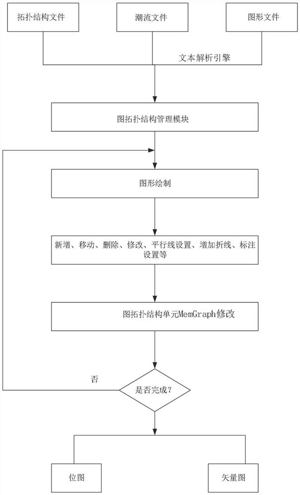
[0137] Such as figure 2 As shown, the generation method of the PSS / E power system power flow wiring diagram based on the graph topology according to the embodiment of the present inv...


PUM


Abstract

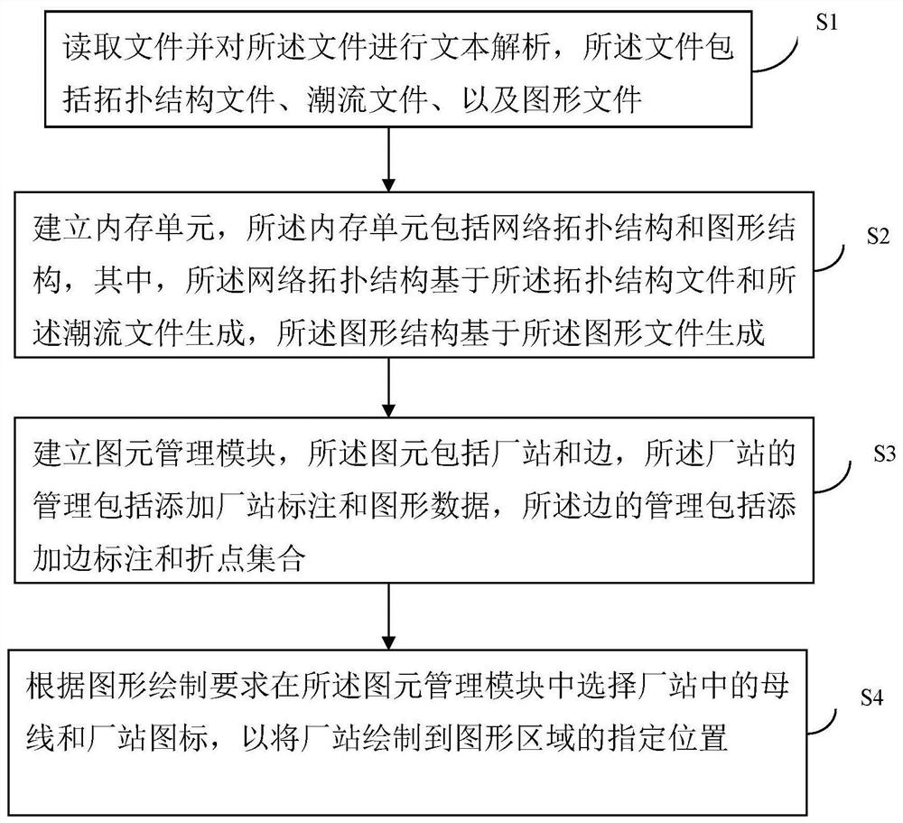
The present invention provides a method for generating a power system power flow wiring diagram, a generating device, an electronic device, and a computer-readable storage medium, wherein the method for generating a power system power flow wiring diagram includes the following steps: Step S1, read the file and The file is analyzed for text, and the file includes a topology file, a power flow file, and a graphic file; step S2, a memory unit is established, and the memory unit includes a network topology and a graph structure, wherein the network topology is based on the topology file Generate with described tidal current file, graphic structure is based on graphic file generation; Step S3, set up graphic element management module, described graphic element comprises plant station and edge, the management of plant station includes adding plant station mark and graphic data, the management of edge includes Add edge labels and vertex sets; step S4, select busbars and plant icons in the plant station in the graphic element management module according to the graphics drawing requirements, so as to draw the plant station to a designated position in the graphics area.

Description

technical field [0001] The invention belongs to the field of power system simulation and calculation analysis, and in particular relates to a generation method, device, electronic equipment, and computer-readable storage medium of a power flow wiring diagram of a PSS / E power system. Background technique [0002] Power system power flow wiring diagram is an indispensable part of power system planning, analysis and engineering calculation. It integrates the grid system network structure, power flow results and graphics, and users can directly view the power flow calculation results of the system. [0003] The power system PSS / E software is one of the most widely used power system analysis software in the power industry in the world. In practical applications, its power flow diagram function has exposed some problems: such as the power plant wiring diagram without hierarchical partition function, the drawing process is cumbersome, The graphics editing function is not perfect, a...

Claims


Application Information

Patent Timeline
Patent Type & Authority Patents(China)
IPC IPC(8): G06F30/392
CPCG06F30/392
Inventor 杜忠明章超王雪松施春华刘世宇戴剑锋邱健刘强张玮灵
Owner 电力规划总院有限公司
Learn More