Antenna and wireless communication device

An antenna and antenna feed point technology, which is applied to antenna equipment, antennas, antenna parts and other directions with additional functions, can solve problems such as interference, and achieve the effects of eliminating influence and reducing production costs

Active Publication Date: 2018-02-09
BEIJING BYTEDANCE NETWORK TECH CO LTD
View PDF4 Cites 5 Cited by
  • Summary
  • Abstract
  • Description
  • Claims
  • Application Information

AI Technical Summary

Problems solved by technology

[0013] In order to solve the above technical problems in the prior art, the present invention provides an antenna and a wireless communication device, which can solve the interference of the USB interface to the antenna in the prior art

Method used


Image

  • Antenna and wireless communication device
  • Antenna and wireless communication device
  • Antenna and wireless communication device

Examples


Embodiment 1

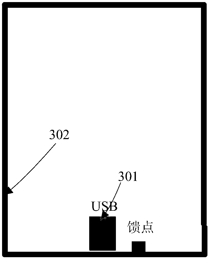
[0055] see image 3 , is a schematic structural diagram of an embodiment of the antenna provided by the present invention.

[0056] The antenna provided in this embodiment includes: a first radiator 301 and a second radiator 302 .

[0057] The second radiator 302 is a seamless closed-loop metal frame.

[0058] The first radiator 301 is a USB interface.

[0059] The metal casing of the USB interface 301 is metal-connected to the second radiator 302 .

[0060] Such as image 3 As shown, the antenna provided in this embodiment has an integrated design for the first radiator 301 and the USB interface, that is, the USB interface can not only perform operations such as data transmission and charging for the device, but also serve as the first radiator to send signals or receive signal. Due to the integrated design, the influence of the original metal shell of the USB interface on the antenna sending and receiving signals is eliminated.

[0061] It should be noted that, in this...

Embodiment 2

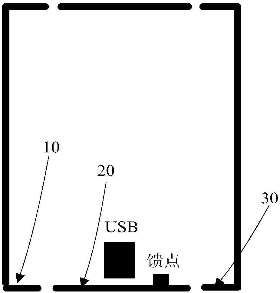
[0070] In order to achieve a better effect of the antenna transmitting and receiving signals, in this embodiment, the antenna feed point is further arranged in the middle of the bottom edge of the second radiator. see Figure 4 , is a schematic structural diagram of another embodiment of the antenna provided by the present invention.

[0071] The antenna provided in this embodiment further includes: an antenna feed point 403 .

[0072] Such as Figure 4 As shown, the antenna feed point 403 may be set at the middle of the bottom edge of the second radiator 402 .

[0073] It should be noted that the setting of the antenna feed point 403 in the middle of the second radiator 402 not only means that the antenna feed point 403 is located in the center of the bottom of the second radiator 402, but also can be slightly left or right, for example, located in the bottom In the left and right predetermined range of the point, the predetermined range is 3mm.

[0074] After research, i...

Embodiment 3

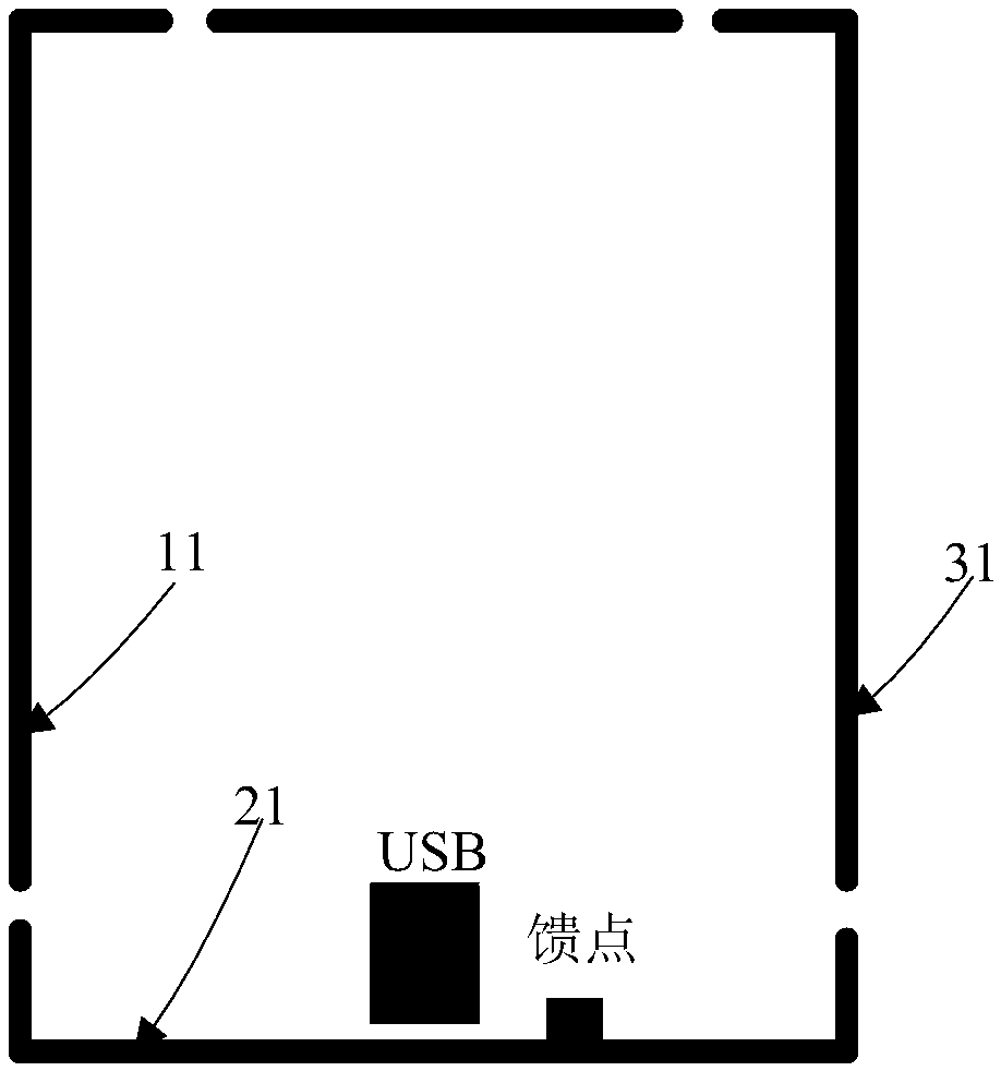
[0080] On the basis of Embodiment 1 and Embodiment 2, the antenna feed point can also be connected to the metal shell of the USB interface. see Figure 5 , is a structural schematic diagram of another embodiment of the antenna provided by the present invention.

[0081] The metal casing of the USB interface 501 is metal-connected to the middle of the bottom edge of the second radiator 502 .

[0082] The antenna feed point 503 is set on the metal shell of the USB interface 501 .

[0083] Such as Figure 5 As shown, the metal casing of the USB interface 501 is connected to the middle of the bottom of the second radiator 502, that is, the USB interface 501 is placed at the middle of the bottom of the metal frame.

[0084] According to the introduction in Embodiment 2, it can be seen that the distance between the antenna feed point and the ground feed will also have a great impact on the antenna receiving and sending signals, and in order to make the effect of the antenna sendi...


PUM


Abstract

The present invention discloses an antenna and a wireless communication device. The antenna comprises a first radiation body and a second radiation body. The second radiation body is a closed-loop metal frame without slots. The first radiation body is a USB interface. A metal shell of the USB interface is connected with metal of the second radiation body. The first radiation body and the USB interface are subjected to integrated design, the second radiation body is designed as the closed-loop metal frame without slots, and the USB interface is connected with the metal of the second radiation body. According to the antenna and the wireless communication device, the first radiation body of the antenna and the USB of the wireless communication device are subjected to integrated design, the effect of the USB interface to antenna receiving and sending signals is eliminated, and on that basis, the antenna is subjected to metal frame closed-loop design, so that production cost is greatly reduced.

Description

technical field [0001] The present invention relates to the technical field of wireless communication, in particular to an antenna and a wireless communication device. Background technique [0002] The function of the antenna is to send and receive signals. For example, mobile phone antennas are also used to send and receive signals. [0003] At present, for the overall appearance of the mobile phone, the mobile phone antenna is required to be hidden inside the mobile phone body, and the antenna cannot be seen from the outside. However, currently, the antennas of mobile phones using metal frames all adopt the design of metal slits. [0004] see figure 1 , which is a schematic structural diagram of an antenna in the prior art. [0005] From figure 1 It can be seen that the antenna includes a first radiator 10 , a second radiator 20 and a third radiator 30 . [0006] Wherein, the second radiator 20 is provided with an antenna feed point. [0007] In addition, another an...

Claims


Application Information

Patent Timeline
Patent Type & Authority Applications(China)
IPC IPC(8): H01Q1/36H01Q1/44H01Q1/24
CPCH01Q1/242H01Q1/36H01Q1/44
Inventor 郝卫东
Owner BEIJING BYTEDANCE NETWORK TECH CO LTD
Why Eureka
Try Eureka