Motor for removing electric corrosion of bearing

A technology of electro-corrosion and bearings, applied in the direction of motor-generator connectors, circuits, electrical components, etc., can solve the problems of high application cost, low versatility, and electro-corrosion application process of motor bearings, and achieve low maintenance cost and versatility Strong, low friction and wear effect

Pending Publication Date: 2018-02-09
HEFEI JUYI POWER SYST CO LTD
View PDF7 Cites 6 Cited by
  • Summary
  • Abstract
  • Description
  • Claims
  • Application Information

AI Technical Summary

Problems solved by technology

[0011] The purpose of the present invention is to provide a motor that eliminates electrical corrosion of bearings, solve the problems of electrical corrosion risk of motor bearings and the difficulty in industrial application process of the prior art, high application cost, low versatility, etc., easy to achieve technically, and multi-platform universal Strong

Method used


Image

  • Motor for removing electric corrosion of bearing
  • Motor for removing electric corrosion of bearing
  • Motor for removing electric corrosion of bearing

Examples


Embodiment 1

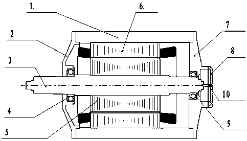
[0034] Such as figure 1 As shown, the motor for eliminating electric corrosion of bearings according to the present invention includes a housing 1 and a motor stator 6 inside it, a motor rotor 5, and a rotating shaft 3, and the two ends of the housing are respectively equipped with a first end cover 2 and a second end cover. Cover 7, one end of the rotating shaft 3 fits through the first end cover 2 through the first bearing 4, the other end of the rotating shaft 3 fits with the second end cover 7 through the second bearing 9, and the second end cover 7 is externally fixed There is a cover plate 8 , and the end surface of the other end of the rotating shaft is electrically connected with the cover plate 8 through an elastic component 10 .

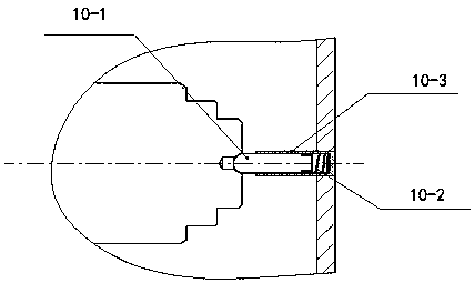
[0035] Such as figure 2 Said, the elastic assembly 10 includes a thimble 10-1, a spring 10-2 and a syringe 10-3, one end of the syringe 10-3 is fixed to the cover plate 8, and the spring 10-2 is placed in the syringe 10-3 Inside, one end...

Embodiment 2

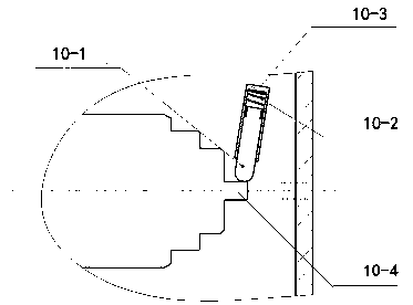
[0039] Such as image 3 As shown, the elastic assembly 10 of this embodiment also includes a thimble 10-1, a spring 10-2 and a needle cylinder 10-3. The difference from Embodiment 1 is that the end surface of the rotating shaft in contact with the thimble 10-1 is processed with a very small The outer diameter of the boss 10-4, the thimble is in radial contact with the boss.

Embodiment 3

[0041] Such as image 3 As shown, the elastic component 10 of this embodiment adopts a spring piece 10 - 5 , one end of the spring piece 10 - 5 is in contact with the cover plate 8 , and the other end is in contact with the end surface of the rotating shaft 3 . The included angle α between the spring leaf 10-5 and the cover plate 8 is larger before the cover plate is installed than after installation, which is equivalent to the principles of embodiments 1 and 2, and the spring leaf can be adjusted to compensate for position changes.


PUM


Abstract

The invention discloses a motor for removing the electric corrosion of a bearing, and the motor comprises a housing, a motor stator, a motor rotor and a rotating shaft, wherein the motor stator, the motor rotor and the rotating shaft are located in the housing. Two ends of the housing are respectively provided with a first end cover and a second end cover. One end of the rotating shaft adaptivelypasses through the first end cover through a first bearing, and the other end of the rotating shaft is adapted to the second end cover through a second bearing. The exterior of the second end cover isfixedly provided with a cover plate, and the end face of the other end of the rotating shaft is electrically connected with the cover plate through an elastic assembly. The cover plate is also electrically connected with the second end cover, the housing, and the first end cover. The elastic assembly comprises an ejector pin, a spring, and a needle cylinder. The exterior of the second end cover is fixedly provided with a cover plate, and one end of the needle cylinder is fixed with the cover plate. The spring is placed in the needle cylinder, wherein one end of the ejector pin stretches intothe needle cylinder to make contact with the spring, and the other end of the ejector pin makes contact with the end face of the rotating shaft. The motor is high in universality, is simple in installation, is low in cost, is long in service life, is reliable in structure, and is low in maintenance cost.

Description

technical field [0001] The invention relates to the field of motors, in particular to a motor for eliminating electric corrosion of bearings. Background technique [0002] A theoretically perfectly balanced three-phase motor operates without shaft voltage. However, due to the fact that the three phases of the motor cannot be perfectly balanced in the manufacturing process, the three phases cannot be perfectly balanced, thus forming an alternating magnetic field inside the motor. Metals generate an electromotive force in an alternating magnetic field. When the motor shaft of metal material is running inside the motor with an alternating magnetic field, an electromotive force will be formed on the shaft. [0003] The electromotive force on the rotating shaft needs to form a loop through the conductor, and the bearing on the motor assumes the role of the conductor in the loop. However, when common bearings are in operation, there is an insulating oil film of about 3 microns ...

Claims


Application Information

Patent Timeline
Patent Type & Authority Applications(China)
IPC IPC(8): H02K11/00H01R13/24
CPCH01R13/2414H01R13/2421H01R13/2442H02K11/0094H01R2201/10
Inventor 刘蕾何靖
Owner HEFEI JUYI POWER SYST CO LTD
Why Eureka
Try Eureka