
Six-bit digital phase shifter
A digital phase shifter, the sixth technology, applied in the field of phase shifters, can solve the problem of low matching degree, achieve the effect of improving phase shifting accuracy and improving the matching between poles
- Summary
- Abstract
- Description
- Claims
- Application Information
AI Technical Summary
Problems solved by technology
Method used
Image


Examples
Embodiment 1
[0023] Such as figure 1 A six-bit digital phase shifter shown includes a 5.625° phase shift circuit, a 11.25° phase shift circuit, a 22.5° phase shift circuit, a 45° phase shift circuit, a 90° phase shift circuit and a 180° phase shift circuit. It is characterized in that the 5.625° phase shift circuit, the 11.25° phase shift circuit, the 22.5° phase shift circuit, and the 45° phase shift circuit are cascaded between the 90° phase shift circuit and the 180° phase shift circuit in any order.
Embodiment 2
[0025] Both 90° phase shift circuit and 180° phase shift circuit can be used as the input terminal of this digital phase shifter, and 5.625° phase shift circuit, 11.25° phase shift circuit, 22.5° phase shift circuit and 45° phase shift circuit can be used in any order Cascading, for example, it can be arranged in order from small to large, or from large to small, or in random order. However, in order to enhance the EDB output power of the phase shifter, the 180° phase shift circuit is used as this The input end of the digital phase shifter, and the 22.5° phase shift circuit, the 45° phase shift circuit, the 11.25° phase shift circuit, and the 5.625° phase shift circuit are cascaded in sequence.
[0026] The circuit with this structure can effectively improve the inter-electrode matching of the phase shifter, and can effectively improve the phase shifting precision.
Embodiment 3
[0028] Based on the principle of the above structure, this embodiment discloses a detailed implementation manner.
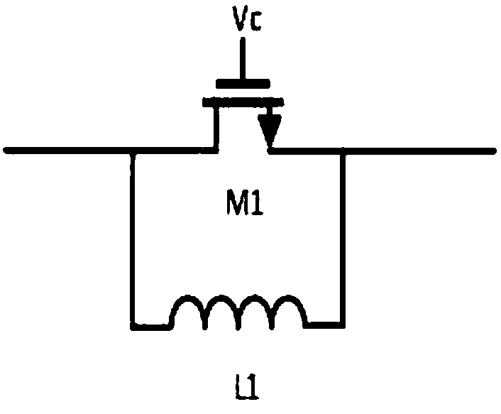
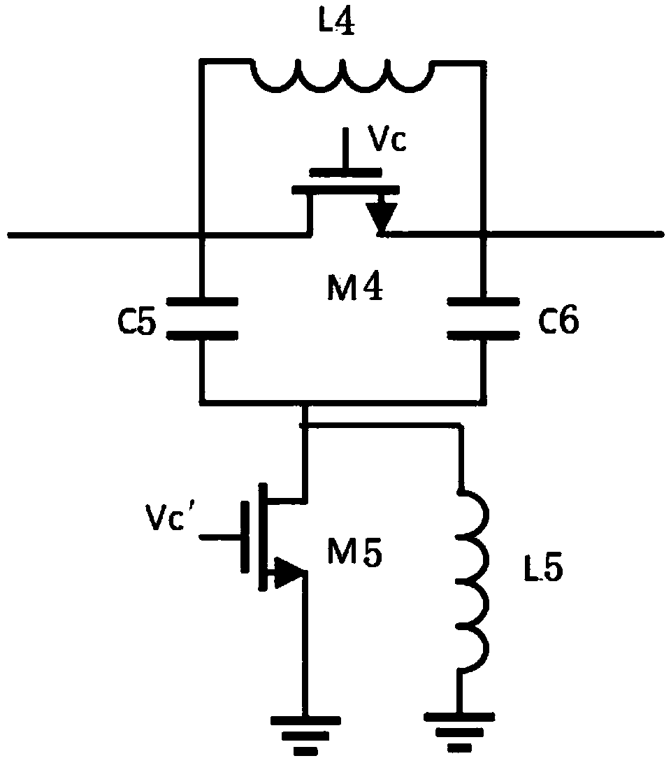
[0029] Such as figure 2 As shown, the 5.625° phase shift circuit includes a first field effect transistor M1, and a first inductor L1 is connected between the source and drain of the first field effect transistor M1. The 5.625° phase shift circuit uses a single switch tube To control, by changing the phase shift of the control relationship, when the first field effect transistor is turned on and the first inductance is large enough, the whole circuit can be regarded as a series resistor, so the phase shift of the circuit is very small, which can be used as a reference position, and the circuit Insertion loss is determined by the size of M1. When the first field effect tube is turned off, the circuit is equivalent to a parallel connection of a capacitor and an inductor, which can generate a small phase shift under the condition of ensuring standing wave performa...
PUM
 Abstract
Description
Claims
Application Information