
Coating machine with tension degree regulating function

A technology of coating machine and tension, which is applied to the surface coating liquid device, coating, etc., can solve the problems of air retention, tape pollution, unreasonable design of rubber rollers, etc., to prevent glue edges and improve Effect of gluing quality, ensuring stability and continuity

Active Publication Date: 2018-02-13
江苏蓝创新材料有限公司
View PDF4 Cites 12 Cited by
  • Summary
  • Abstract
  • Description
  • Claims
  • Application Information

AI Technical Summary

Problems solved by technology

[0004] At present, when producing single-sided tape, glue rollers are usually used to apply glue to the tape. Due to the unreasonable design of the glue roller, there will be glue edges on both sides of the tape. When the tape is stacked or wound, the glue edge of the tape will be layered Layers accumulate, so it is easy to make air stay between the layers of tapes, resulting in loose contact between the layers of tapes, which is easy to cause pollution inside the tapes; the existing tape production equipment lacks a device for adjusting the tension of the tapes. During the process, the tape is prone to looseness, which will lead to unqualified production quality and equipment shutdown, which will seriously affect the normal production and operation of the equipment.

Method used


Image

  • Coating machine with tension degree regulating function
  • Coating machine with tension degree regulating function
  • Coating machine with tension degree regulating function

Examples


Embodiment Construction

[0019] It should be noted that, in the case of no conflict, the embodiments of the present invention and the features in the embodiments can be combined with each other.

[0020] In describing the present invention, it should be understood that the terms "center", "longitudinal", "transverse", "upper", "lower", "front", "rear", "left", "right", " The orientations or positional relationships indicated by "vertical", "horizontal", "top", "bottom", "inner" and "outer" are based on the orientations or positional relationships shown in the drawings, and are only for the convenience of describing the present invention and Simplified descriptions, rather than indicating or implying that the device or element referred to must have a particular orientation, be constructed and operate in a particular orientation, and thus should not be construed as limiting the invention. In addition, the terms "first", "second", etc. are used for descriptive purposes only, and should not be understood ...


PUM


Abstract

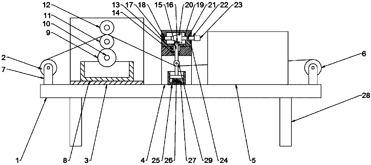
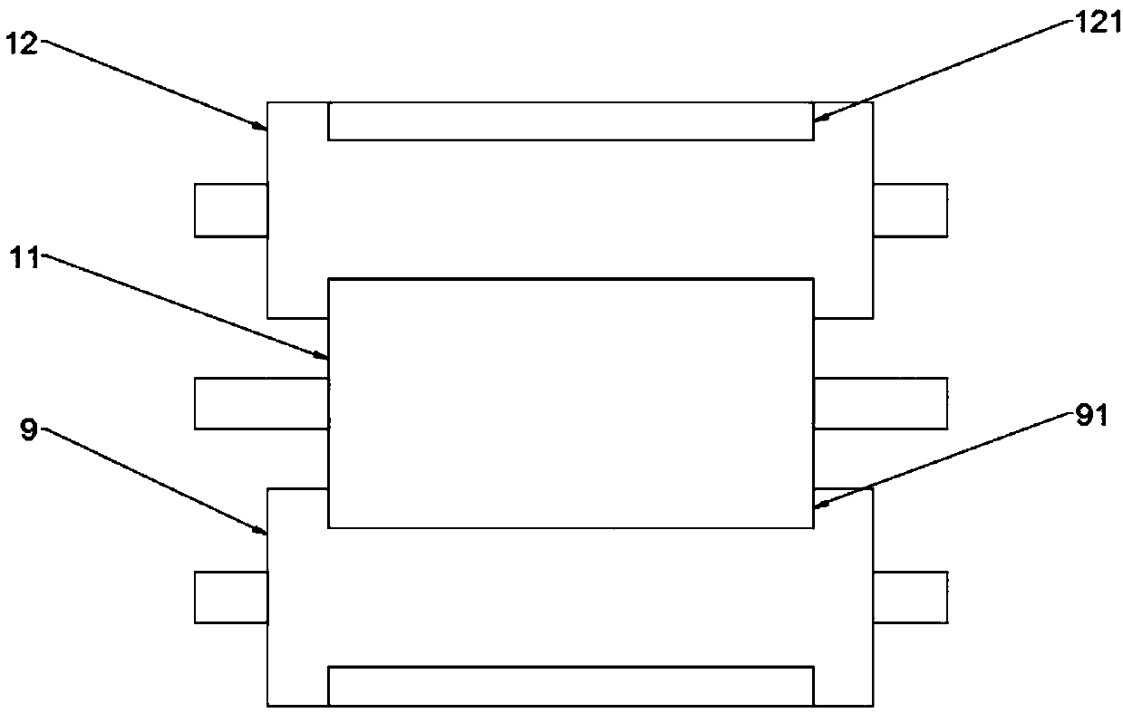
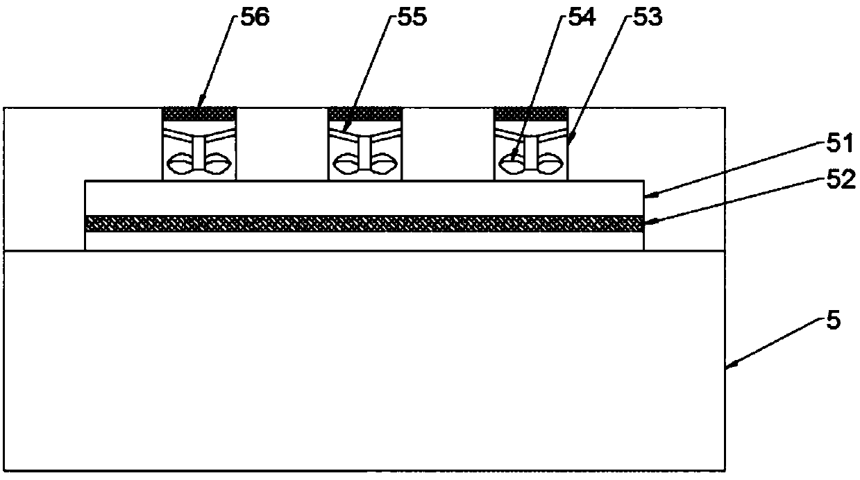
The invention discloses a coating machine with a tension degree regulating function. The coating function comprises a workbench. An unreeling roll, a gluing box, a tension regulating box, a drying boxand a reeling roll are arranged at the top end of the workbench sequentially from left to right. A glue storage box is arranged at the bottom wall of an inner cavity of the gluing box. A gluing rollmatched with the glue storage box is rotationally connected to the bottom of the inner cavity of the gluing box through a rotating shaft. A guide roll is connected with the top of the inner cavity ofthe gluing box rotationally through a rotating shaft. A communicating hole is formed in the top end of the tension regulating box. A guide sleeve is arranged at the bottom of the communicating hole. Alifting rod is arranged in the guide sleeve. A support seat box corresponding to the tension regulating box is fixedly connected to the top end face of the workbench. A plurality of support legs areevenly arranged at the bottom end of the workbench. The coating machine has the advantages that through interworking among the gluing roll, a scraping roll and the guide roll with special structures,trimmings can be prevented effectively, so that gluing quality is improved; through the tension regulating box, regulation can be made timely according to tension degrees of adhesive tapes, and accordingly, production stability and continuity are guaranteed.

Description

technical field [0001] The invention relates to the field of adhesive tape production devices, in particular to a coating machine with the function of adjusting tension. Background technique [0002] Scotch tape was invented by Richard Drew in St. Paul, Minnesota, USA in 1928. Adhesive tapes can be divided into high temperature tapes, double-sided tapes, insulating tapes, special tapes, pressure-sensitive tapes, and die-cut tapes according to their functions. Different functions are suitable for different industry needs. A layer of adhesive is coated on the surface of the tape to make the tape stick to the object. The earliest adhesives came from animals and plants. In the 19th century, rubber was the main component of the adhesive; in modern times, various polymers are widely used. [0003] Adhesive tape is composed of base material and adhesive, which connects two or more unconnected objects together by bonding. Its surface is coated with a layer of adhesive. The earlie...

Claims


Application Information

Patent Timeline
Patent Type & Authority Applications(China)
IPC IPC(8): B05C1/08B05C13/02
CPCB05C1/0834B05C13/02
Inventor 曹茂娟
Owner 江苏蓝创新材料有限公司
Learn More