
Charging pile lifting system

A lifting system and charging pile technology, applied in charging stations, electric vehicle charging technology, electric vehicles and other directions, can solve the problem of charging piles occupying ground space and other problems, and achieve the effects of simple structure, convenient life and convenient maintenance

Inactive Publication Date: 2018-02-13
安徽灵图壹智能科技有限公司
View PDF4 Cites 2 Cited by
  • Summary
  • Abstract
  • Description
  • Claims
  • Application Information

AI Technical Summary

Problems solved by technology

[0005] The purpose of the present invention is to overcome the problem that the construction of charging piles needs to occupy a certain amount of ground space in the prior art

Method used


Image

  • Charging pile lifting system

Examples


Embodiment 1

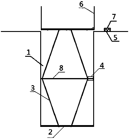
[0016] This embodiment provides a figure 1 The charging pile lifting system shown is characterized in that it includes a cavity 1 located below the ground level and a lifting device 2 fixedly installed at the bottom of the cavity 1 .

[0017] Specifically, the lifting device 2 includes a scissor jack 3 and a motor 4 , the stator of the motor 4 is fixedly connected to the scissor jack 3 , and the rotor of the motor 4 is fixedly connected to a screw rod 8 .

[0018] It should be noted that the lifting device 2 further includes a control switch 5 arranged on the ground plane close to the cavity 1 , and the control switch 5 is electrically connected with the motor 4 .

[0019] In particular, a protective fence 6 is provided on the top of the scissor jack 3 .

[0020] It should be pointed out that the control switch 5 is provided with an outer cover 7 .

[0021] As a preferred technical solution, the outer cover 7 is made of waterproof material.

[0022] The charging pile liftin...


PUM


Abstract

The invention relates to a charging pile lifting system which comprises a cavity formed under a ground plane and a lifting device fixedly installed at the bottom of the cavity. The problem that a certain ground space is occupied for construction of a charging pile, a control switch housing specially made of a waterproof material guarantees safe and stable operation of the device, convenience is provided for life, and the charging pile lifting system is simple in structure and convenient to maintain.

Description

technical field [0001] The invention belongs to the field of power supply systems, and in particular relates to a charging pile lifting system. Background technique [0002] As the global auto industry is facing huge challenges of energy and environmental issues, there has been a broad international consensus on the development of new energy electric vehicles, the electrification of automotive energy and power systems, and the promotion of the strategic transformation of the traditional auto industry. As a green transportation tool with broad development prospects, electric vehicles will be popularized very rapidly in the future, and the future market prospects will be extremely huge. At present, the Chinese government is actively promoting the application and development of new energy vehicles. As an important supporting infrastructure necessary for the development of electric vehicles, charging / swapping stations have very important social and economic benefits. A movement...

Claims


Application Information

Patent Timeline
Patent Type & Authority Applications(China)
IPC IPC(8): B60L11/18
CPCB60L53/30B60L53/31Y02T10/70Y02T10/7072Y02T90/12
Inventor 赵宏丽
Owner 安徽灵图壹智能科技有限公司
Learn More