Lifting appliance special for bridge type crane

A bridge crane and spreader technology, which is applied in the direction of walking bridge cranes, cranes, load blocks, etc., can solve the problems of low efficiency, shortened service life, and increased wear of bridge cranes, and achieves simple suspension operation, The effect of increasing service life and accelerating work efficiency

Inactive Publication Date: 2018-02-13
ANHU WUHU CHANGJIANG JACK UP EQUIP CO LTD
View PDF6 Cites 0 Cited by
  • Summary
  • Abstract
  • Description
  • Claims
  • Application Information

AI Technical Summary

Problems solved by technology

[0003] With frequent production activities and heavy tasks, coupled with the deformation of the girder of the bridge crane and the deterioration of the crown rail, the wear and tear of the bridge crane is increased and the service life is shortened; moreover, the existing bridge crane can only suspend one crane at a time. Items, so it is also less efficient in the work process

Method used


Image

  • Lifting appliance special for bridge type crane
  • Lifting appliance special for bridge type crane

Examples


Embodiment

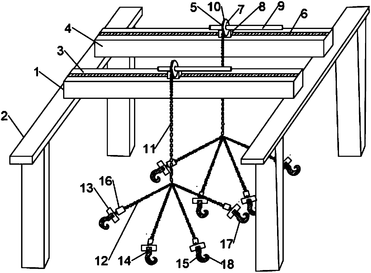
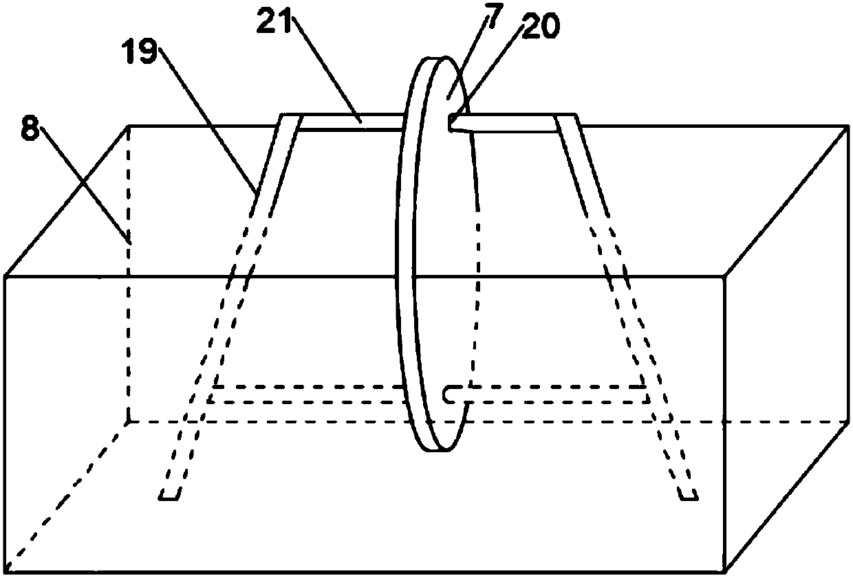
[0023] Such as figure 1 with figure 2 As shown, it includes a bridge 1 and a viaduct 2. The bridge 1 is set directly above the viaduct 2. The bridge 1 can move longitudinally along the viaduct 2. The bridge 1 includes a main girder 3 and a secondary girder 4. The beam 3 and the auxiliary beam 4 are both box-type structures. The upper surfaces of the main beam 3 and the auxiliary beam 4 are provided with a traction device 5, and the traction device 5 includes a rail 6 and a reel 7, and the rail 6 is welded to On the upper surface of the main beam 3 and the sub-beam 4, a slider 8 is provided above the rail 6. The slider 8 has a hollow structure, and the slider 8 can follow the rail under the control of the control system. 6 accurately move laterally to transport the material to the desired position. The reel 7 is arranged at the upper end of the slider 8, and the slider 8 moves laterally along the rail 6 above the rail 6, thereby driving the reel 7 along The rail 6 moves latera...


PUM


Abstract

The invention discloses a lifting appliance special for a bridge type crane. The lifting appliance comprises a bridge and an overhead part. The bridge comprises a main beam and an auxiliary beam whichare each of a box-type structure, traction devices are arranged on the upper surfaces of the main beam and the auxiliary beam correspondingly and comprise tracks and rolls, and the tracks are weldedto the upper surfaces of the main beam and the auxiliary beam. Sliding blocks are arranged above the tracks and can move along the tracks transversely. The rolls are arranged at the upper ends of thesliding blocks, the centers of the rolls are provided with rotary shafts, and one ends of the rotary shafts are connected with motors through belts. Grooves are formed in the outer surfaces of the rolls, the interiors of the grooves are wound with steel wire ropes, and one ends of the steel wire ropes extend to the lower end of the bridge. A plurality of branches are arranged at the lower ends ofthe steel wire ropes, the top ends of the branches and the steel wire ropes are hinged together, and the bottom ends of the branches are provided with hanging rings. The hanging rings are connected with hangers through screws. The structure is simple, operation is easy and convenient, the function of material hanging can be achieved, the problems put forward by the background technology can be effectively solved, and the lifting appliance is worth popularizing.

Description

Technical field [0001] The invention relates to the technical field of lifting equipment, in particular to a special spreader for bridge cranes. Background technique [0002] The bridge crane is a lifting equipment that is horizontally framed over the workshop, warehouse and material yard for material lifting. Because its two ends are located on tall concrete columns or metal supports, it is named after the shape of a bridge. The bridge of the bridge crane runs longitudinally along the tracks laid on the elevated sides on both sides, which can make full use of the space under the bridge to lift materials , Not hindered by ground equipment, it is the most widely used and the largest number of cranes. [0003] With frequent production activities and heavy tasks, coupled with the deformation of the bridge crane beam and the deterioration of the crane track, the bridge crane wears more and the service life is shortened; moreover, the existing bridge crane can only be suspended one at ...

Claims


Application Information

Patent Timeline
IPC IPC(8): B66C17/26B66C13/06B66C11/00B66C1/14
CPCB66C1/14B66C11/00B66C13/06B66C17/26
Inventor 焦来文
Owner ANHU WUHU CHANGJIANG JACK UP EQUIP CO LTD
Why Eureka
Try Eureka