
I-beam joint structure preventing flowing around body and water seeping of underground diaphragm wall and construction method thereof

An underground diaphragm wall and joint structure technology, which is applied in infrastructure engineering, sheet pile walls, buildings, etc., can solve the problems of concrete bypass, incomplete cleaning of joints, easy water leakage at the joints of underground diaphragm walls, etc. The effect of preventing bypass and avoiding water leakage

Pending Publication Date: 2018-02-13
TAIYUAN UNIV OF TECH
View PDF4 Cites 6 Cited by
  • Summary
  • Abstract
  • Description
  • Claims
  • Application Information

AI Technical Summary

Problems solved by technology

However, due to the error of the verticality of the groove and the protective layer of the steel bar, the ordinary I-beam joint is prone to concrete flow. At the same time, due to the use of mud wall protection during the groove formation process, the joint is not cleaned thoroughly and there is mud inclusion, which makes the underground continuous wall connection Seams are prone to water leakage

Method used


Image

  • I-beam joint structure preventing flowing around body and water seeping of underground diaphragm wall and construction method thereof
  • I-beam joint structure preventing flowing around body and water seeping of underground diaphragm wall and construction method thereof
  • I-beam joint structure preventing flowing around body and water seeping of underground diaphragm wall and construction method thereof

Examples


Embodiment Construction

[0026] In order to further illustrate the content, features and effects of the present invention, the present invention will be described in detail with reference to the accompanying drawings and embodiments.

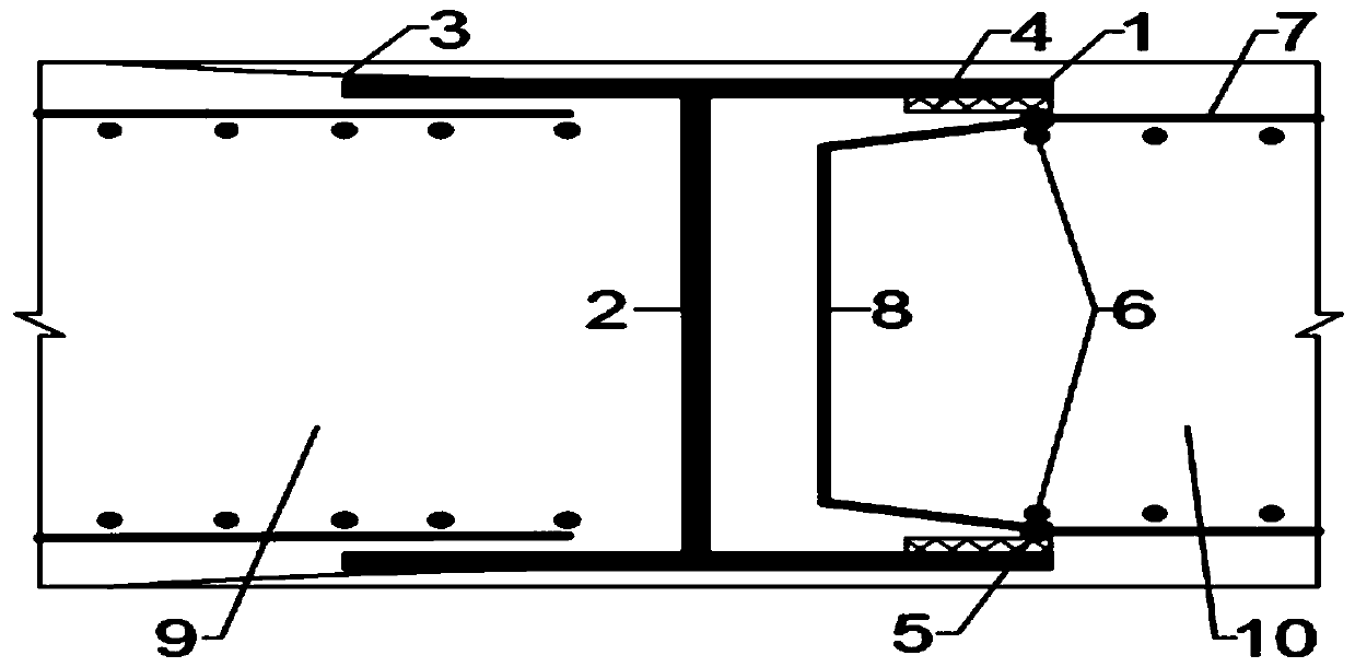
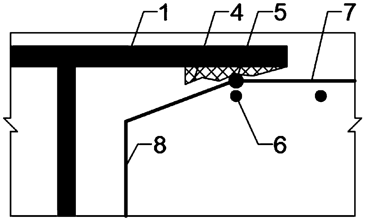
[0027] An underground diaphragm wall anti-circumvention and anti-seepage water I-shaped steel joint structure, wherein the joint structure is composed of I-shaped steel welded by two wing plate steels 1 and one web steel 2, anti-slip iron sheet 3, rubber The waterstop 4, the sealing vertical rib 5 at the corner of the steel cage end of the subsequent trough section, and the edge foot 11 at the bottom of the I-shaped steel joint are composed.

[0028] Such as figure 1 As shown, the inner side of the wing plate steel on one side of the I-beam is welded with the horizontally distributed ribs 7 of the reinforcement cage 9 of the previous groove section to form a whole, and the outer side of the wing plate steel on the side of the I-beam is respectively welded with the anti-...


PUM

PropertyMeasurementUnit
Lengthaaaaaaaaaa

Abstract

The invention discloses an I-beam joint structure preventing flowing around a body and water seeping of an underground diaphragm wall and a construction method thereof. The joint structure is composedof an I-beam formed by welding two pieces of wing plate section steel to one piece of web section steel, grout stopping iron sheets, rubber water stopping belts, vertical sealing ribs at the cornersof the ends of a subsequent slot section, blade feet on the bottom of the I-beam joint and the like; the inner sides of the wing plate section steel of the I-beam joint are welded to horizontally distributed ribs of an early slot section, and the grout stopping iron sheets are welded to the outer sides of the wing plate section steel; the rubber water stopping belts stick to the inner sides of thewing plates of the I-beam of the subsequent slot section by means of binder; the vertical sealing ribs are welded at the corners of the ends of a subsequent slot section steel reinforcement cage. According to the joint structure, the integrity is good, construction is easy, the problem that concrete flows around a body is effectively prevented, the anti-seepage effect in a joint is good, and thestructure is applicable to joint connection of an ultra deep underground diaphragm wall.

Description

technical field [0001] The invention belongs to the field of underground diaphragm wall construction in underground engineering, and specifically relates to an underground diaphragm wall anti-circumvention and anti-seepage water I-shaped steel joint structure and a construction method. Background technique [0002] The underground diaphragm wall has the functions of retaining soil and preventing seepage. At the same time, it is widely used in deep foundation pit engineering because of its advantages such as high overall rigidity, small construction vibration, and strong stratum adaptability. The underground diaphragm wall is composed of unit groove sections connected to each other through joints. The quality of the joints is directly related to the integrity of the wall structure and the reliability of anti-seepage, and even more related to the safety of the entire project. [0003] I-beam joints are currently widely used in the joint construction of underground diaphragm wa...

Claims


Application Information

Patent Timeline
IPC IPC(8): E02D5/20E02D19/18
CPCE02D5/20E02D19/18E02D19/185E02D2250/0023
Inventor 杨欢欢杨双锁郭子奇牛少卿鲍飞翔糜瑞杰
Owner TAIYUAN UNIV OF TECH
Learn More