Underground diaphragm wall joint, clamping device matched with underground diaphragm wall joint and underground diaphragm wall construction method

A technology of a clamping device and a construction method, which is applied to artificial islands, water conservancy projects, infrastructure projects, etc., can solve the problems of difficulty in fixing the locking pipe, difficult to grasp the lifting and pulling, and the installation of the locking pipe is skewed, etc. The effect of reliable compactness, reduction of production cost and time saving

Active Publication Date: 2014-07-02
CHINA RAILWAY CONSTR BRIDGE ENG BUREAU GRP NO 4 ENG
View PDF4 Cites 2 Cited by
  • Summary
  • Abstract
  • Description
  • Claims
  • Application Information

AI Technical Summary

Problems solved by technology

[0011] In order to solve the problems that the groove wall is not vertical in the construction of the existing locking tube, the installation of the locking tube is skewed and not in place, it is difficult to fix th

Method used


Image

  • Underground diaphragm wall joint, clamping device matched with underground diaphragm wall joint and underground diaphragm wall construction method
  • Underground diaphragm wall joint, clamping device matched with underground diaphragm wall joint and underground diaphragm wall construction method
  • Underground diaphragm wall joint, clamping device matched with underground diaphragm wall joint and underground diaphragm wall construction method

Examples


specific Embodiment approach 1

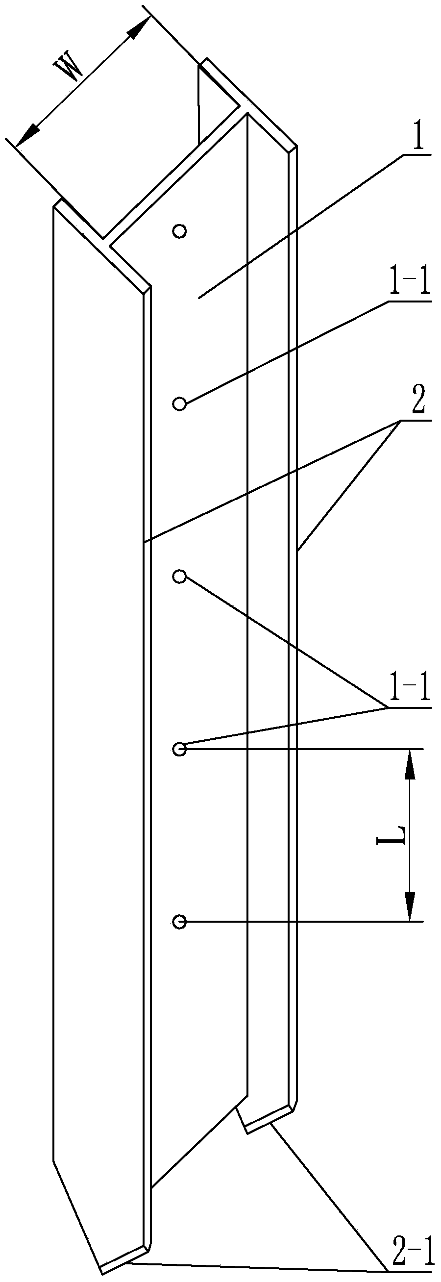
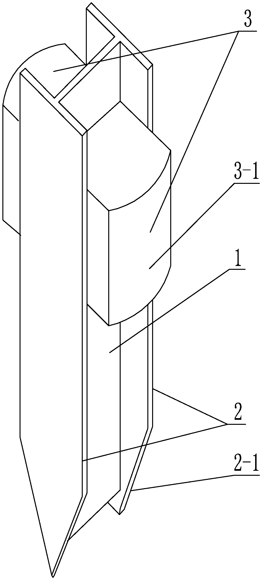
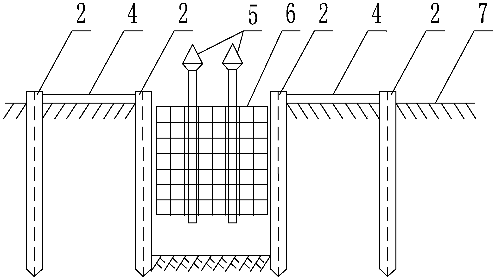
[0031] Specific implementation mode one: as Figure 1~2 As shown, the ground connection wall joint of this embodiment includes a web 1 and two side plates 2, the two side plates 2 are arranged in parallel and facing each other, and the two side plates 2 are fixed in one body through the web 1 along the length direction, and the two side plates 2 The two side plates 2 are arranged vertically to the web 1, the cross-section of the ground connection wall joint is "H" shaped, the lower ends of the two side plates 2 are processed with a bevel 2-1, and the width W of the web 1 is 550~ 650mm, the web 1 is uniformly processed with a plurality of circular through-holes 1-1 along its length direction, the diameter of the circular through-holes 1-1 is 100-110mm, and the diameter of two adjacent circular through-holes 1-1 The center distance L is 1750-1850mm.

[0032] The length of the ground connection wall joint of the present invention is made on site according to the designed wall de...

specific Embodiment approach 2

[0033] Specific implementation mode two: as figure 1 As shown, the width W of the web 1 in this embodiment is 600 mm.

[0034] Such design is to consider that the conventional design thickness of the connecting wall is used in the case of 1000mm, and the width W can be adjusted according to the designed connecting wall thickness. Other components and connections are the same as those in the first embodiment.

specific Embodiment approach 3

[0035] Specific implementation mode three: as figure 1 As shown, the diameter of the circular through hole 1-1 in this embodiment is 105mm. This design is to ensure that the 100mm diameter stud bolts pass through and fix the two side plates smoothly. Other compositions and connections are the same as those in Embodiment 1 or 2.


PUM

PropertyMeasurementUnit
Widthaaaaaaaaaa

Abstract

The invention provides an underground diaphragm wall joint, a clamping device matched with the underground diaphragm wall joint and an underground diaphragm wall construction method and relates to the underground diaphragm wall joint and the underground diaphragm wall construction method in order to solve the problems that slurry walls are out of plumb, lock catch tubes are installed obliquely or not in place and are hard to fix, and the pulling time of the lock catch tubes is hard to grasp in the construction process of the existing lock catch tubes. The underground diaphragm wall joint is characterized in that two side plates are fixedly connected into a whole through a web plate in the length direction, the cross section of the underground diaphragm wall joint is in an H shape, the lower end of each side plate is provided with an edge angle, a plurality of round through holes are evenly formed in the web plate in the length direction, and two cast steel balancing weights are fixed to the positions above the round through holes in the web plate through bolts and nuts. The underground diaphragm wall construction method includes the steps of carrying out guide wall construction, determining a position, assembling the clamping device, pressing the underground diaphragm wall joint into a soil body, dismantling clamping units, cleaning a groove, hoisting and placing a steel reinforcement cage into the groove, pouring concrete and directly carrying out excavation construction beside the groove after the concrete strength meets requirements. The underground diaphragm wall joint, the clamping device matched with the underground diaphragm wall joint and the underground diaphragm wall construction method are applied to construction of underground diaphragm walls.

Description

technical field [0001] The invention relates to a ground connection wall joint, a matching clamping device and a ground connection wall construction method, belonging to the construction field of ground connection wall structures. Background technique [0002] At present, the ground connection wall is an underground maintenance structure introduced into China in 1958. Due to the high rigidity, high bearing capacity and good anti-seepage performance of the ground connection wall, it can be used for reverse construction and is suitable for various foundation conditions. It is widely used in many aspects of various foundation projects such as subways, coal, and municipal projects. It is a continuous underground wall with anti-seepage (water), soil retaining and load-bearing functions. [0003] The construction method of the underground diaphragm wall is as follows: surveying, building guide wall, making steel cage, mud preparation, digging groove, clearing groove, lowering loc...

Claims


Application Information

Patent Timeline
IPC IPC(8): E02D29/16E02D29/02
Inventor 邸志鲲巩晓辉付宏亮
Owner CHINA RAILWAY CONSTR BRIDGE ENG BUREAU GRP NO 4 ENG
Why Eureka
Try Eureka