Transmission Oil Filter Assembly

a technology of filter assembly and transmission oil, which is applied in the direction of gearing details, filtration separation, separation processes, etc., can solve the problems of excessive pressure drop across the filter, stuck valves, and less effective functions, and achieve the effect of preventing bypass flow

Inactive Publication Date: 2016-11-24
FORD GLOBAL TECH LLC
View PDF4 Cites 3 Cited by
  • Summary
  • Abstract
  • Description
  • Claims
  • Application Information

AI Technical Summary

Benefits of technology

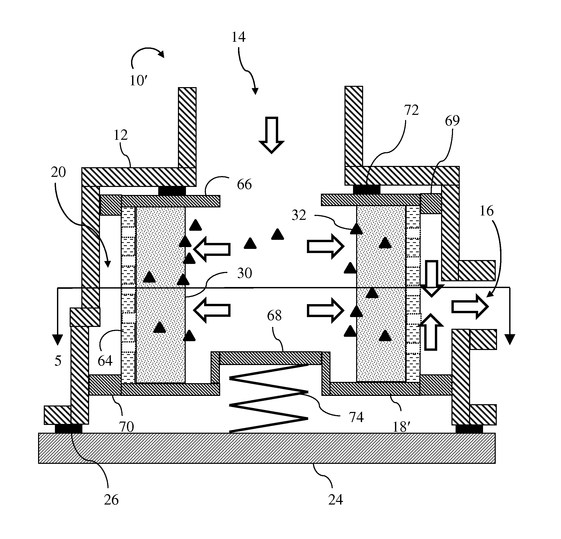
[0005]A transmission includes a hydraulic pump, a control system, a housing defining a filter chamber, a filter cartridge, and a spring biasing the filter cartridge toward a first position within the filter chamber. The pump draws fluid from a sump and supplies the fluid at increased pressure to a pump outlet circuit. The control system routes fluid from a line pressure circuit to transmission clutches. The filter chamber includes an inlet port connected to the pump outlet circuit and an outlet port connected to the line pressure circuit. When the filter is in the first position within the filter chamber, fluid is constrained to flow through filter media in the filter cartridge. If the pressure difference between the pump outlet circuit and the line pressure circuit exceeds a threshold, the filter cartridge slides within the filter chamber to a second position in which fluid may bypass the filter media. The transmission may also include a removable cover which provides access to replace the filter cartridge when the filter media is saturated with contaminants. In the first position, a face seal between the filter cartridge and the chamber may prevent bypass flow. Two sets of axially spaced tabs position the filter cartridge radially within the filter chamber while permitting circumferential flow around the cartridge.

Problems solved by technology

When the fluid contain contaminants, it may be less effective in these functions and may cause failures such as stuck valves.
When the temperature of the fluid is very cold, such as shortly after starting the vehicle during the winter, the viscosity can be very high causing the pressure drop across the filter to be excessive.
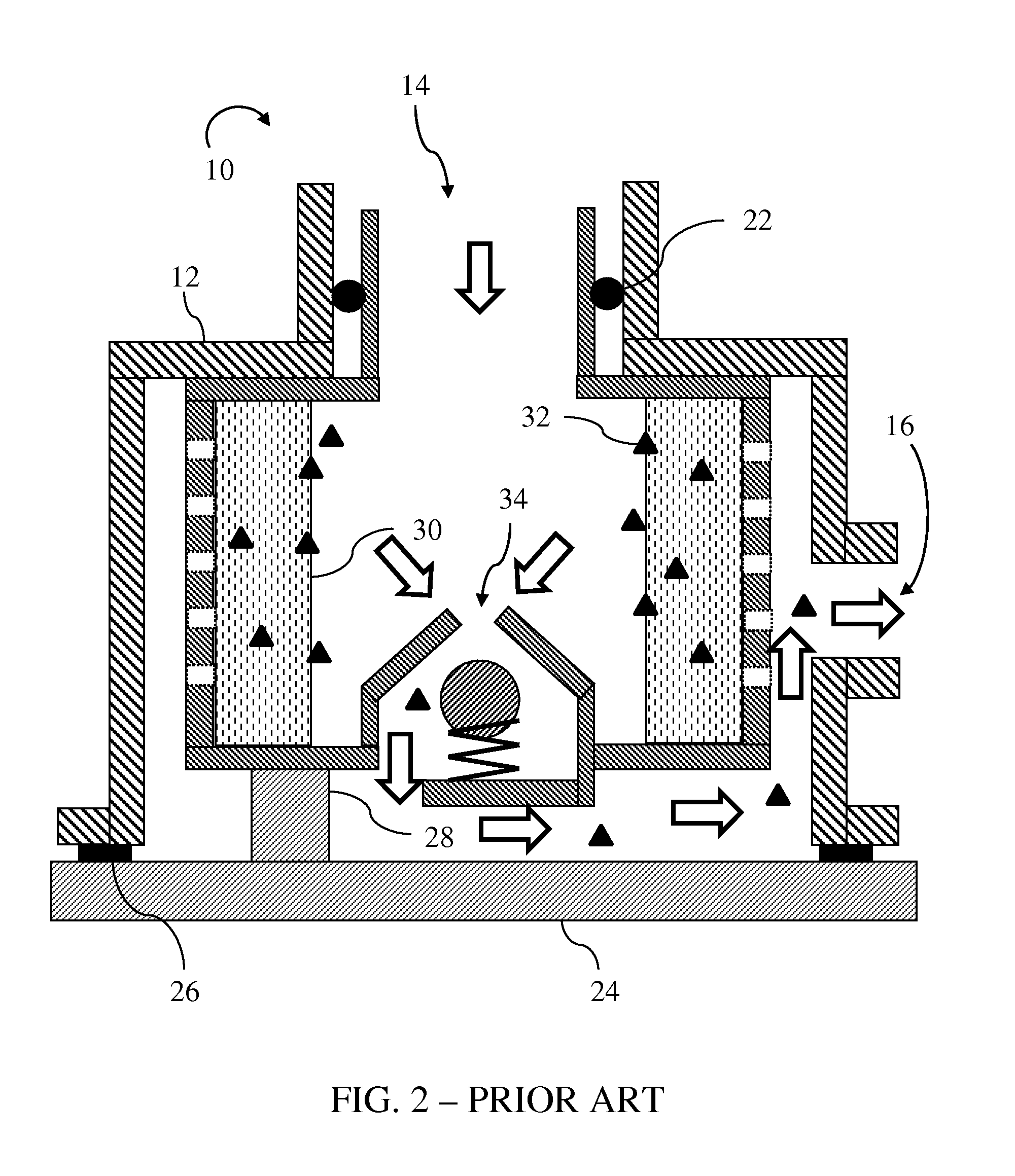
However, since the fluid passes close to the filter media on its way to the relief valve, some of the previously captured contaminant may re-enter the fluid.

Method used


Image

  • Transmission Oil Filter Assembly
  • Transmission Oil Filter Assembly
  • Transmission Oil Filter Assembly

Examples


Embodiment Construction

[0013]Embodiments of the present disclosure are described herein. It is to be understood, however, that the disclosed embodiments are merely examples and other embodiments can take various and alternative forms. The figures are not necessarily to scale; some features could be exaggerated or minimized to show details of particular components. Therefore, specific structural and functional details disclosed herein are not to be interpreted as limiting, but merely as a representative basis for teaching one skilled in the art to variously employ the present invention. As those of ordinary skill in the art will understand, various features illustrated and described with reference to any one of the figures can be combined with features illustrated in one or more other figures to produce embodiments that are not explicitly illustrated or described. The combinations of features illustrated provide representative embodiments for typical applications. Various combinations and modifications of ...


PUM

PropertyMeasurementUnit
pressureaaaaaaaaaa
pressureaaaaaaaaaa
transmissionaaaaaaaaaa

Abstract

A transmission filter assembly utilizes a filter cartridge that slides axially with respect to the filter chamber. In normal operation, a spring pushes the filter cartridge into a position such that fluid flows into the interior of the cartridge, through filter media, and then radially out of the cartridge. If the pressure drop across the filter is excessive, the pressure forces the filter cartridge to slide to a position in which fluid bypasses the filter media. In this bypass mode, fluid does not flow into the interior of the cartridge and therefore has a very low tendency to dislodge previously captured contaminants. Two sets of tabs position the cartridge radially within the chamber. The two sets are separated axially to prevent tilting of the cartridge.

Description

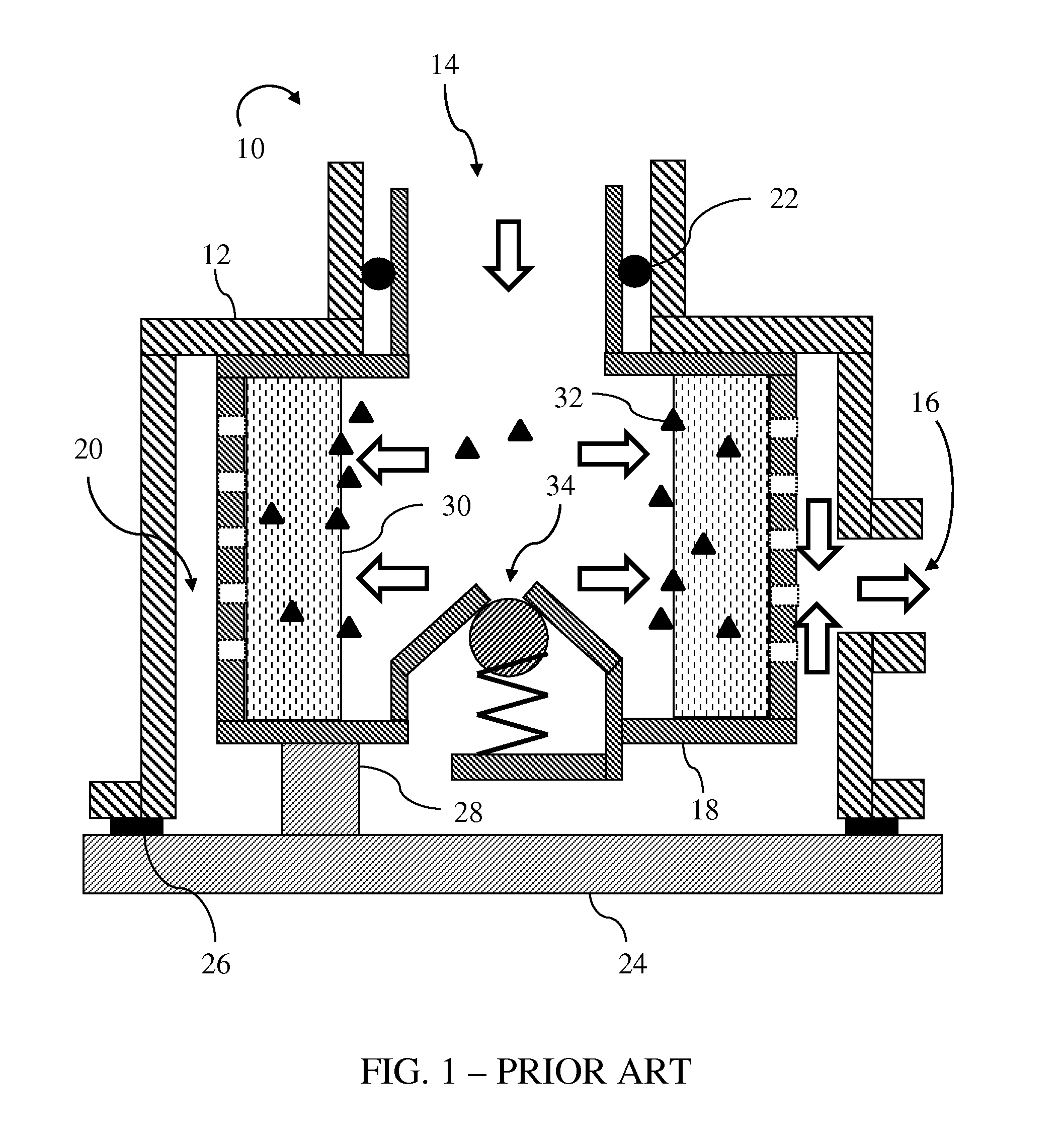
TECHNICAL FIELD[0001]This disclosure relates to the field of transmission systems. More particularly, the disclosure pertains to a filter assembly with improved pressure relief functionality.BACKGROUND[0002]Automatic transmission fluid serves many functions in a modern automatic transmission. Pressurized fluid may be used engage friction clutches in order to establish a power flow path with a desired speed ratio. Fluid lubricates gears and bearings. Excess heat is removed by fluid flowing over various components. When the fluid contain contaminants, it may be less effective in these functions and may cause failures such as stuck valves. Therefore, transmissions often include fluid filters.[0003]FIG. 1 is a cross section of a type of transmission filter 10. A housing 12 defines a filter chamber having an inlet port 14 and an outlet port 16. A filter cartridge 18 is located within the chamber. An inlet of the cartridge extends into inlet port 14 which positions the cartridge radially....

Claims


Application Information

Patent Timeline
Patent Type & Authority Applications(United States)
IPC IPC(8): F16H57/04B01D35/147B01D35/30B01D29/96B01D35/00
CPCF16H57/0404B01D29/96B01D35/1475B01D35/30B01D35/005B01D29/25B01D29/88B01D35/147B01D29/23B01D2201/295
Inventor PEKARSKY, LEVYASNOGORODSKIY, VLADIMIRZAMAN, AKHTERKANE, MARK JOSEPH
Owner FORD GLOBAL TECH LLC
Why Eureka
Try Eureka