Construction method for preventing diaphragm wall from streaming

A construction method, the technology of ground connection wall, applied in the direction of excavation, sheet pile wall, foundation structure engineering, etc., to achieve the effect of tight combination, no bypass flow, and easy operation

Inactive Publication Date: 2012-11-14
THE FIFTH ENG CO LTD OF CHINA TIESIJU CIVIL ENG GRP
View PDF5 Cites 3 Cited by
  • Summary
  • Abstract
  • Description
  • Claims
  • Application Information

AI Technical Summary

Problems solved by technology

[0006] The purpose of the present invention is to provide a construction method for preventing flow around the ground connection wall, thereby solving the problem of tight combination of concrete and I-beam joints in the second phase of the groove section during the construction of the ground connection wall

Method used


Image

  • Construction method for preventing diaphragm wall from streaming
  • Construction method for preventing diaphragm wall from streaming
  • Construction method for preventing diaphragm wall from streaming

Examples


Embodiment

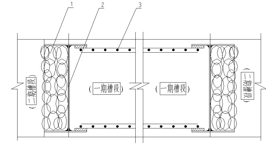
[0018] Throw and fill sand bags behind the I-beam in the first-stage trough section, and then compact it with a cuboid steel box hammer. See( figure 1 ) Schematic diagram of the location of the sand bag.

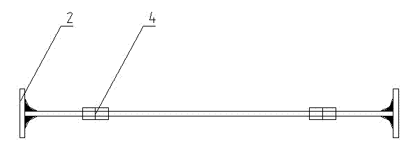
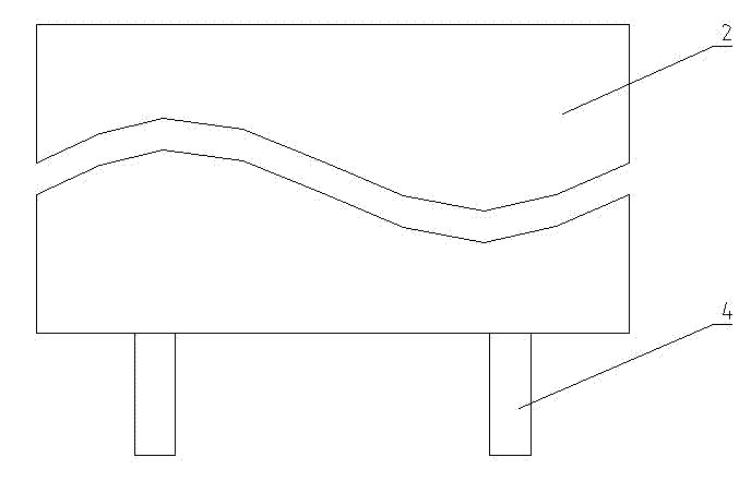
[0019] Since the elevation of the top of the ground connection wall is generally below the ground, it is difficult to control the position when throwing and filling the sand bag. Therefore, it is necessary to process an I-steel member with a slot, which is connected to the I-steel of the reinforcement cage 3 of the ground connection wall. , perforate the upper part of the component, thread the wire rope and the lock; the lower part adopts a card slot, and clamp the component on the steel cage I-beam. After the underwater concrete pouring of the ground connection wall is completed, the I-beam steel member is taken out. See( figure 2 , 3 , 4) I-beam card channel steel components.

[0020] The sand bag is a small-volume ordinary woven bag, filled with 1 / 3 of the volume of...


PUM


Abstract

A construction method for preventing diaphragm wall from streaming comprises the following steps of: filling a plurality of sand bags behind an I-beam of a primary slot section, wherein the sand bags are small-volume normal woven bags filled with 1/3 volume of sand, bag mouths are tied firmly and the bags are paved, the sand in the bags are loose, and the bags are arranged behind the I-beam, and beaten and compacted by a steel box hammer so that the sand bags are filled behind the I-beam completely; repeating the operation till the whole process is finished; and taking out the filled sand bags when drilling during a secondary slot section. With the adoption of the method, the purpose of tight connection between the concrete of the secondary slot section and the I-beam joint in the diaphragm wall construction is achieved. The construction method has the characteristics of being convenient in construction and easy in operation, the streaming of concrete is avoided, the concrete of the secondary slot section is tightly combined with the I-beam joint, and the water leakage rate of the underground diaphragm wall is reduced.

Description

technical field [0001] This patent relates to a construction method for preventing flow around a ground connection wall. Background technique [0002] Under the complex soft soil geological conditions of urban subway deep foundation pits, the enclosure structure mostly adopts the ground connection wall and internal support structure system. There are two types of ground-to-wall joints: lock pipe joints and I-beam joints. However, in areas with rich groundwater and high confined water, I-steel joints are often used as the joint method of the ground connection wall. Most of them use joint plates. The disadvantages of this method of construction are: [0003] (1) The groove is generally over-excavated, and the width of the groove is larger than the design width, but the width of the joint plate is generally the same as the design width of the groove section, which cannot completely block the flow of concrete to the second-stage groove section; [0004] (2) During the con...

Claims


Application Information

Patent Timeline
Patent Type & Authority Applications(China)
IPC IPC(8): E02D5/20E02D17/04E02D19/18
Inventor 鲍俊捷索晓华卢志军
Owner THE FIFTH ENG CO LTD OF CHINA TIESIJU CIVIL ENG GRP
Why Eureka
Try Eureka