Underground diaphragm wall reinforcement cage structure with formworks and construction method of underground diaphragm wall reinforcement cage structure

A technology of underground diaphragm walls and steel cages, which is applied in foundation structure engineering, sheet pile walls, buildings, etc., can solve problems that affect the quality of the project, and achieve the goals of ensuring the thickness of the protective layer, improving joint waterproofing and overall waterproofing, and improving flatness Effect

Inactive Publication Date: 2021-10-29
CHINA RAILWAY SHANGHAI ENGINEERING BUREAU GROUP CO LTD +1
View PDF5 Cites 2 Cited by
  • Summary
  • Abstract
  • Description
  • Claims
  • Application Information

AI Technical Summary

Problems solved by technology

If the external water pressure is high, water seepage will occur during the pouring of the concrete wall, which will seriously affect the quality of the project

Method used


Image

  • Underground diaphragm wall reinforcement cage structure with formworks and construction method of underground diaphragm wall reinforcement cage structure

Examples


Embodiment 1

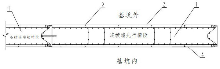
[0014] An underground continuous wall reinforcement cage structure with formwork, comprising a ground connection wall reinforcement cage 1, the bottom end and both side surfaces of the ground connection wall reinforcement cage 1 (the two surfaces connected with the foundation pit) are provided with steel plates.

Embodiment 2

[0016] An underground continuous wall reinforcement cage structure with formwork, comprising a ground connection wall reinforcement cage 1, the bottom end and both side surfaces of the ground connection wall reinforcement cage 1 (the two surfaces connected with the foundation pit) are provided with steel plates.

[0017] Further, several channel steels 2 are welded on the bottom and both sides of the ground wall reinforcement cage 1, and the ground wall reinforcement cage 1 is provided with steel plates through the channel steels.

Embodiment 3

[0019] An underground continuous wall reinforcement cage structure with formwork, comprising a ground connection wall reinforcement cage 1, the bottom end and both side surfaces of the ground connection wall reinforcement cage 1 (the two surfaces connected with the foundation pit) are provided with steel plates.

[0020] Further, several channel steels 2 are welded on both sides of the ground connection wall reinforcement cage 1, and the ground connection wall reinforcement cage 1 is provided with steel plates through the channel steels.

[0021] Further, the channel steel 2 is welded to the steel plate or bonded with an adhesive, specifically: the steel plate on the outer surface of the ground wall reinforcement cage 1 is a stainless steel plate 3, and the ground wall reinforcement cage 1 is welded to the stainless steel plate 3 through the channel steel ; The steel plate on the inner surface of the ground wall reinforcement cage 1 is an ordinary steel plate 4, and the ground ...


PUM


Abstract

The invention belongs to the technical field of municipal engineering underground diaphragm wall construction, and particularly relates to an underground diaphragm wall reinforcement cage structure with formworks and a construction method of the underground diaphragm wall reinforcement cage structure. The underground diaphragm wall reinforcement cage structure comprises an underground diaphragm wall reinforcement cage, and steel plates are arranged at the bottom end and on the two side surfaces of the underground diaphragm wall reinforcement cage. Multiple pieces of channel steel are welded to the two side surfaces of the underground diaphragm wall reinforcement cage, and the underground diaphragm wall reinforcement cage is provided with the steel plates through the channel steel. The channel steel is welded with the steel plates or is in adhesive connection with the steel plates through an adhesive. The steel plate on the outer side surface of the underground diaphragm wall reinforcement cage is a stainless steel plate, and the underground diaphragm wall reinforcement cage is welded with the stainless steel plate through the channel steel; and the steel plate on the inner side surface of the underground diaphragm wall reinforcement cage is a common steel plate, and the underground diaphragm wall reinforcement cage is in adhesive connection with the common steel plate through the channel steel by using the adhesive. According to the invention, the steel plate formworks are between the inner and outer surfaces of a preset underground diaphragm wall and a soil body, the surface quality and the internal compactness of concrete are improved, a continuous waterproof layer is formed on the outer surface of the diaphragm wall, and the leakage and seepage resistance of the underground diaphragm wall is greatly improved.

Description

technical field [0001] The invention belongs to the technical field of underground diaphragm wall construction in municipal engineering, and in particular relates to an underground diaphragm wall reinforced cage structure with formwork and a construction method thereof. Background technique [0002] Existing underground continuous wall adopts a kind of groove digging machine (grooving machine) on the ground, along the center line of the guide wall completed in advance, and under the condition of mud retaining wall, a narrow and long deep groove is excavated in sections, clearing After the trough, hang the reinforcement cage in the trough, and then use the conduit method to pour underwater concrete to form a unit trough section, so that a continuous reinforced concrete wall is built underground as a water interception, seepage prevention, and load bearing. , Water retaining structure. If the external water pressure is high, water seepage will occur during the pouring of the ...

Claims


Application Information

Patent Timeline
Patent Type & Authority Applications(China)
IPC IPC(8): E02D5/18E02D15/00
CPCE02D5/18E02D5/187E02D5/182E02D15/00
Inventor 周洪光章安忠高星星黄显青户少勇
Owner CHINA RAILWAY SHANGHAI ENGINEERING BUREAU GROUP CO LTD
Why Eureka
Try Eureka