Broken nail removal device for orthopedics department

A removal device, orthopedic technology, applied in medical science, surgery, fixator and other directions, can solve the problems of increasing patient pain, large bone damage, inability to rotate, etc., and achieve the effect of reducing operation difficulty, small bone damage, and convenient operation.

Inactive Publication Date: 2018-02-16
鲁海江
View PDF5 Cites 1 Cited by
  • Summary
  • Abstract
  • Description
  • Claims
  • Application Information

AI Technical Summary

Problems solved by technology

However, although the removal process of the hollow nail is relatively simple, it often happens that the hollow nail cannot be rotated, and some bone nails are tightly combined with the bone, causing the bone nail to break and damage, so that the forceps extractor has to be used. The bone is more destructive, causing unnecessary pain to the patient
[0003] In the prior art, in the process of taking out the broken nail, the broken nail often cannot be fixed, the broken nail slips, the cross section is uneven, and it cannot be rotated. This situation leads to some patients who cannot take out the broken nail after the fracture has healed, or use a relatively destructive method to remove the broken nail. or traumatic removal
[0004] The broken nail removal device is a commonly used medical device in orthopedics. The existing broken nail removal device usually engraves external threads on the surface of the broken nail when used, and the tapper needs to be moved along the outer ring of the broken nail during the calibration process. Rotation, greater bone damage, increased patient pain

Method used


Image

  • Broken nail removal device for orthopedics department
  • Broken nail removal device for orthopedics department
  • Broken nail removal device for orthopedics department

Examples


Embodiment

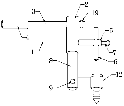
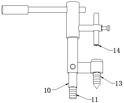
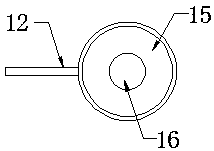
[0025] Example: such as Figure 1-4 As shown, a device for removing broken orthopedic nails of the present invention includes a device body 1, a main rod 2 is arranged on the device body 1, a cross bar 3 is detachably connected to one side of the main rod 2, and a cross bar 3 is detachably connected to the main rod 2 The other side is fixedly installed with a first installation side bar 5, which is movably connected with a connecting rod 6, and the bottom of the connecting rod 6 is welded with a chuck 14, and the side of the first installation side bar 5 is A limit bolt 7 is installed at the end, and the connecting rod 6 is fixedly connected with the first installation side rod 5 through the limit bolt 7. The bottom of the main rod 2 is fixedly connected with a telescopic main rod 8, and the telescopic main rod 8. A second installation side bar 12 is fixedly connected to the bottom of one side, and a punching mechanism 13 is detachably connected to the second installation side...


PUM


Abstract

The invention discloses a broken nail removal device for the orthopedics department. The broken nail removal device comprises a device body, the device body is provided with a main rod, one side of the main rod is detachably connected with a horizontal rod, a first mounting side rod is fixedly mounted at the other side of the main rod and movably connected with a connecting rod, a clamping head iswelded to the bottom of the connecting rod, a limit bolt is mounted at the side end of the first mounting side rod, the connecting rod is fixedly connected with the first mounting side rod through the limit bolt, and the bottom of the main rod is fixedly connected with a retractable main rod; the broken nail removal device is provided with a punching mechanism and a nail removal head, a threadeddrill bit is arranged on the punching mechanism, and a threaded hole can be drilled in a broken nail through the threaded drill bit and then is in threaded connection with the threaded drill bit through the nail removal head so that the broken nail can be removed by rotating the horizontal rod. The broken nail removal device is reasonable in structure and convenient to operate, compared with traditional modes of etching outer threads on broken nails, damage to bones is smaller, and the pain of patients is relieved.

Description

Technical field: [0001] The invention relates to the technical field of medical aids, in particular to a device for removing broken orthopedic nails. Background technique: [0002] In orthopedic surgery, internal fixation with screws combined with steel plates and hollow nails is a commonly used method, because hollow nails have structural advantages that ordinary screws do not have, so hollow nails are used very frequently. However, although the removal process of the hollow nail is relatively simple, it often happens that the hollow nail cannot be rotated, and some bone nails are tightly combined with the bone, causing the bone nail to break and damage, so that the forceps extractor has to be used. The bone is more destructive, causing unnecessary pain to the patient. [0003] In the prior art, in the process of taking out the broken nail, the broken nail often cannot be fixed, the broken nail slips, the cross section is uneven, and it cannot be rotated. This situation le...

Claims


Application Information

Patent Timeline
Patent Type & Authority Applications(China)
IPC IPC(8): A61B17/92
CPCA61B17/92A61B2017/564
Inventor 于朝用
Owner 鲁海江
Why Eureka
Try Eureka