
Power module dust removing method, system and device and computer readable storage medium

A technology for power modules and fans, applied in cleaning methods and utensils, chemical instruments and methods, and cleaning methods using gas flow, etc., can solve the problems of uncontrollable internal temperature of the cavity, steady state break of thermal cycle, dust accumulation, etc.

Active Publication Date: 2018-02-16
KEHUA DATA CO LTD +1
View PDF6 Cites 8 Cited by
  • Summary
  • Abstract
  • Description
  • Claims
  • Application Information

AI Technical Summary

Problems solved by technology

When the power module works under low load for a long time, the speed of the fan is stable at a low speed, so the inside of the cavity of the power module is in a steady state of thermal cycle, and the dust is in a relatively static state, which leads to the accumulation of dust inside the cavity of the power module. With the increase of dust accumulation, the thermal cycle stability inside the cavity of the power module will be broken
Therefore, under low load, the original fan speed cannot control the internal temperature of the cavity within the preset range
At this time, if the load increases, even if the fan speed increases, due to the influence of dust accumulation, the internal heat dissipation of the module will be slow, causing the power module to easily trigger the over-temperature protection
[0003] It can be seen that the power module works under low load for a long time, which will easily cause dust accumulation. If the dust is not removed in time, the dust will become thicker and thicker with time. Difficult to remove stubborn dust buildup
[0004] In addition, long-term dust accumulation will reduce the heat dissipation capacity of the power module, thereby reducing the service life of the power module

Method used

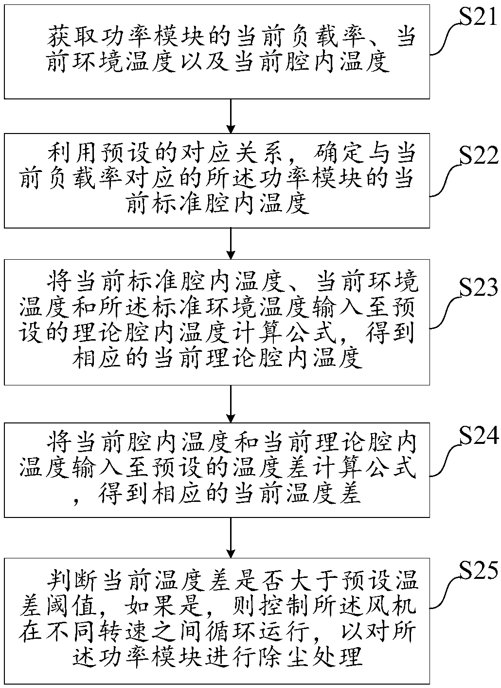
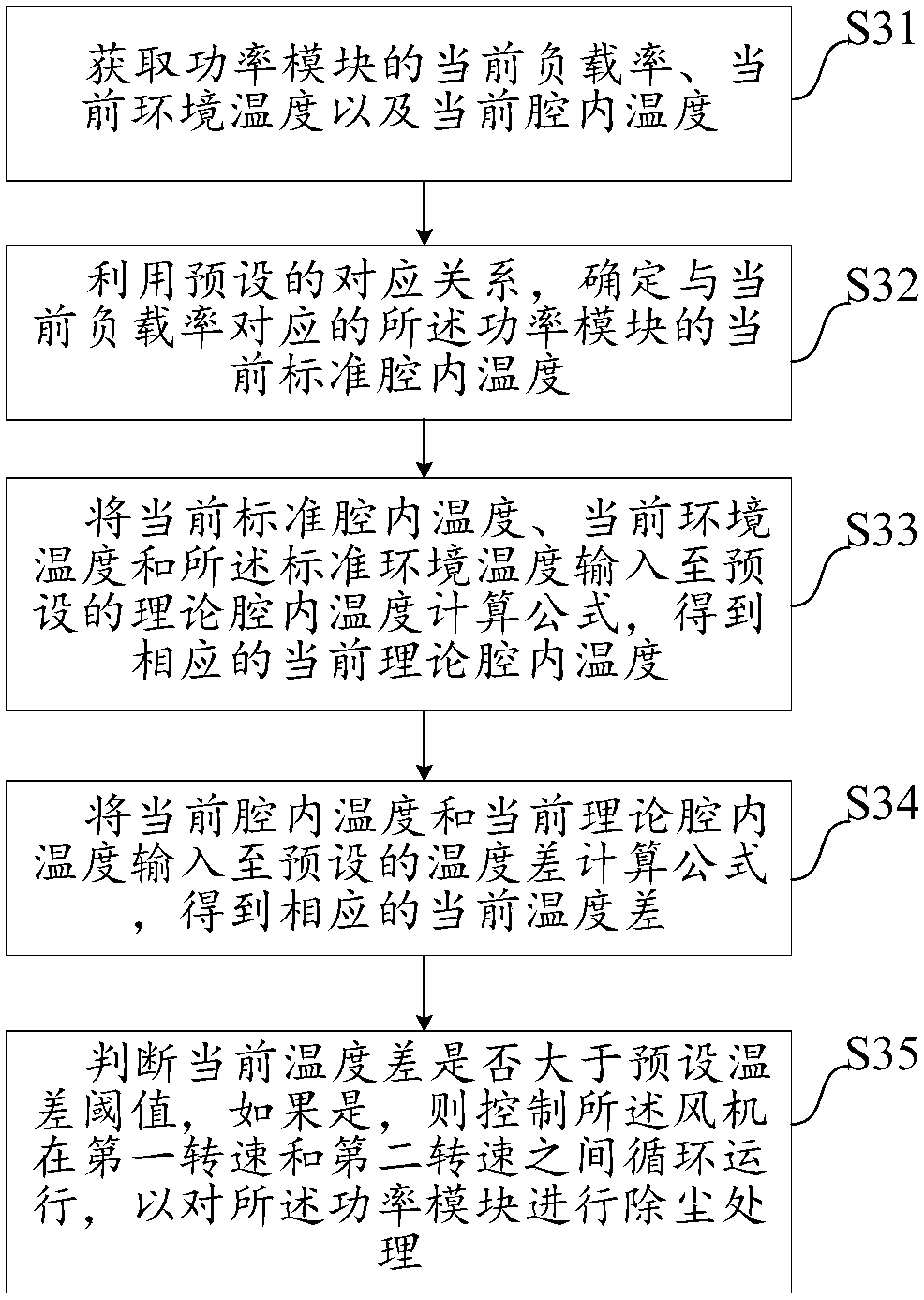

Image

  • Power module dust removing method, system and device and computer readable storage medium
  • Power module dust removing method, system and device and computer readable storage medium
  • Power module dust removing method, system and device and computer readable storage medium

Examples


Embodiment Construction

[0052] The following will clearly and completely describe the technical solutions in the embodiments of the present invention with reference to the accompanying drawings in the embodiments of the present invention. Obviously, the described embodiments are only some, not all, embodiments of the present invention. Based on the embodiments of the present invention, all other embodiments obtained by persons of ordinary skill in the art without making creative efforts belong to the protection scope of the present invention.

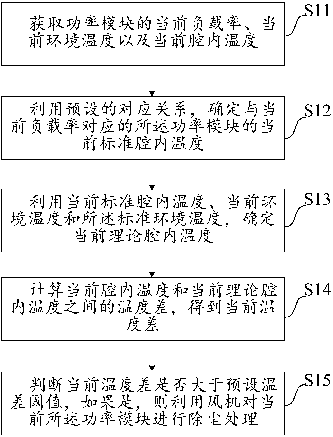
[0053] The embodiment of the present invention discloses a power module dust removal method, see figure 1 As shown, the method includes:

[0054] Step S11: Obtain the current load rate, current ambient temperature and current cavity temperature of the power module.

[0055] In the embodiment of the present application, the above-mentioned power module can be an integrated circuit module that undertakes high power in the circuit, such as a power module in the ...


PUM


Abstract

The invention discloses a power module dust removing method, system and device and a computer readable storage medium. The method comprises the steps that the current load rate, the current environment temperature and the current cavity interior temperature of a power module are obtained, the current standard cavity interior temperature corresponding to the current load rate is determined according to the corresponding relation, established at the standard environment temperature, between the load rate and the standard cavity interior temperature; and on the basis of the above conditions, thecurrent theoretical cavity interior temperature can be determined, accordingly, the current temperature difference can be obtained through calculation, and if the current temperature difference is larger than or equal to the preset temperature difference threshold value, a draught fan is utilized for conducting dust removing treatment on the power module. According to the power module dust removing method, system and device and the computer readable storage medium, through real-time knowing of the load rate of the power module and the temperature rise situation in a cavity, the current dust accumulation situation is inferred, the draught fan is utilized for conducting dust removal on the power module in time, the problem that heat dissipation of the power module is slow under the low loaddue to dust accumulation is solved, and the service life of the power module is prolonged.

Description

technical field [0001] The invention relates to the field of dust removal, in particular to a power module dust removal method, system, equipment and computer-readable storage medium. Background technique [0002] With the development of science and technology, power modules are an indispensable part of most fields. It is inevitable that almost all power modules need to consider the problem of heat dissipation. So far, fans have been widely used for heat dissipation of various power modules, such as dust removal, ventilation and cooling in communication equipment, vehicles, air conditioning equipment and household electrical appliances, and the current fans generally have the function of speed regulation, in other words , each load has a fan speed corresponding to it. When the power module works under low load for a long time, the speed of the fan is stable at a low speed, so the inside of the cavity of the power module is in a steady state of thermal cycle, and the dust is...

Claims


Application Information

Patent Timeline
IPC IPC(8): B08B5/00
CPCB08B5/00
Inventor 刘艺超江东升陈迪叶柄
Owner KEHUA DATA CO LTD
Learn More