Tool for turn milling
A tooling, turning and milling technology, applied in the direction of manufacturing tools, other manufacturing equipment/tools, etc., can solve the problems of affecting the processing efficiency, increasing the process time beat, and cannot guarantee the coaxiality error of the outer cylindrical surface and the sealing groove, etc., to achieve the guarantee Effect of Concentricity Requirements
- Summary
- Abstract
- Description
- Claims
- Application Information
AI Technical Summary
Problems solved by technology
Method used
Image

Examples
Embodiment 1
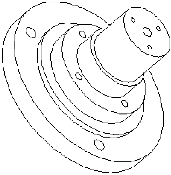
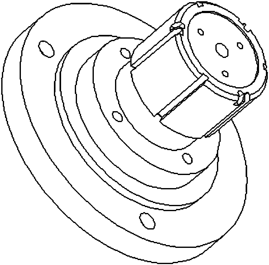
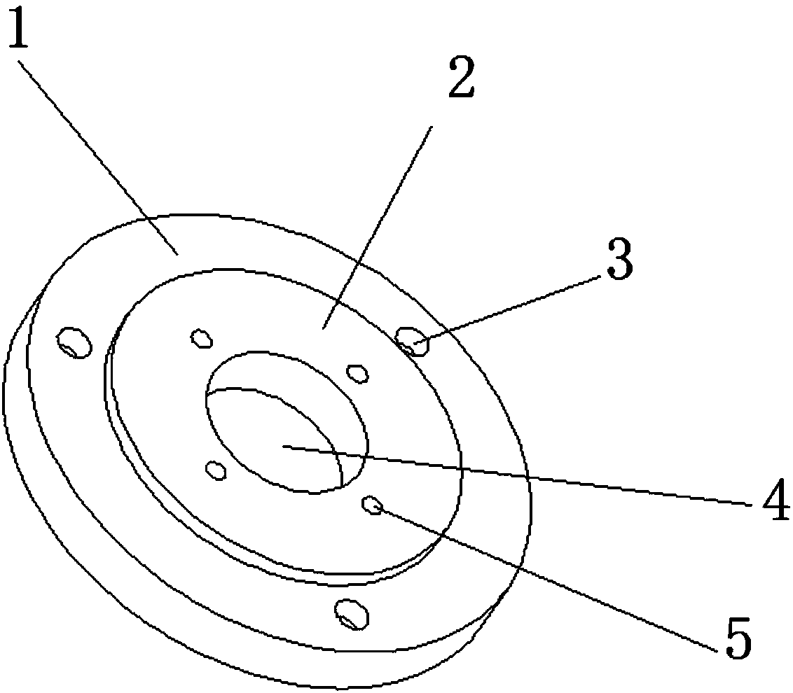
[0024] Embodiment 1: as Figure 1~4 The shown tooling for turning and milling includes a chuck connector and a stepped positioning shaft. The chuck connector is sequentially arranged with a flange structure connector chassis 1 and a connector boss 2 along the same axis, and its The outer diameter becomes smaller in turn, and there is a through-clamping hole 4 for clamping and positioning of the gripper along the axis of the chuck connector. The stepped positioning shaft is successively arranged with the positioning shaft chassis 7 of cylindrical structure, the positioning shaft boss 8 and the mandrel 9 along the same axis, and its outer diameter becomes smaller successively. The outer diameter of the mandrel 9 is the same as that of the workpiece to be processed The inner diameters are the same, and at this time, the workpiece to be processed can be set on the mandrel 9 in an interference fit manner. In addition, a positioning block can also be installed on the upper surface ...
PUM
 Abstract
Description
Claims
Application Information
 - R&D
- Intellectual Property
- Life Sciences
- Materials
- Tech Scout
- Unparalleled Data Quality
- Higher Quality Content
- 60% Fewer Hallucinations
Browse by: Latest US Patents, China's latest patents, Technical Efficacy Thesaurus, Application Domain, Technology Topic, Popular Technical Reports.
© 2025 PatSnap. All rights reserved.Legal|Privacy policy|Modern Slavery Act Transparency Statement|Sitemap|About US| Contact US: help@patsnap.com