Special-purpose disk spring type clamping and loosening device of lathe

The technology of a special lathe and a disc spring is applied in the field of disc spring type clamping and releasing devices for special lathes, which can solve the problem that the coaxiality of the processed workpiece cannot meet the specified requirements, the assembly and maintenance are inconvenient, and the expansion of the chuck is uneven, etc. problems, to achieve the effect of simple structure, convenient assembly and maintenance, and improved service life

Inactive Publication Date: 2015-12-16
北京一川创业数控设备有限责任公司
View PDF8 Cites 5 Cited by
  • Summary
  • Abstract
  • Description
  • Claims
  • Application Information

AI Technical Summary

Problems solved by technology

[0002] The clamping mechanism used in the original CNC lathe, because the center of the chuck is tightened by the conical surface, the conical surface is easy to tilt during the expansion process, and the chuck expands unevenly, making it difficult for the coaxiality of the workpiece to meet the specified requirements.
The clamping mechanism used in the original CNC lathe, because the disc spring assembly is loaded from the rear end of the spindle box, it is inconvenient to assemble and maintain
The clamping mechanism used in the original CNC lathe uses a rotary cylinder for the power part to loosen the workpiece. During the processing, the main shaft part rotates at high speed, and the joint part of the rotary cylinder is prone to heat, thus reducing the service life.

Method used


Image

  • Special-purpose disk spring type clamping and loosening device of lathe

Examples


Embodiment Construction

[0015] The present invention will be described in detail below in conjunction with the accompanying drawings and embodiments.

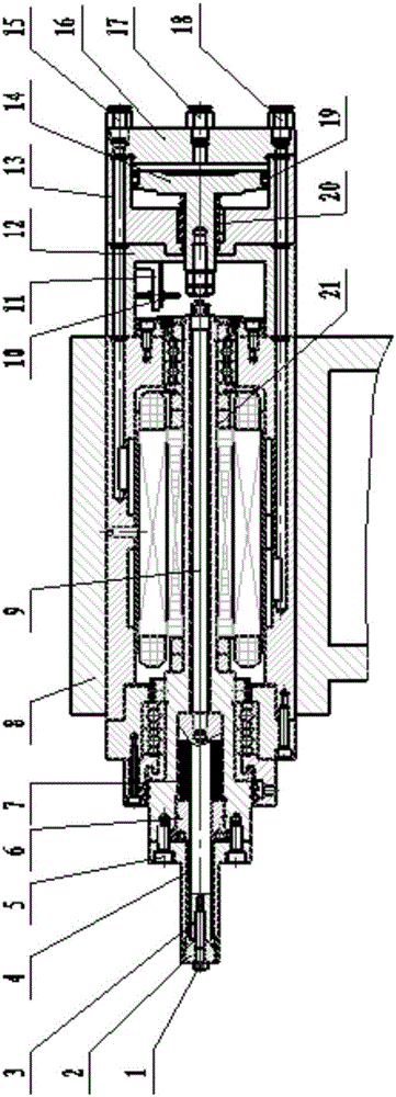
[0016] like figure 1 As shown, the electric spindle 21 is installed in the spindle box 8, which together constitute the main part of the spindle. The push rod 9 is sleeved on the hollow part of the electric spindle 21, one end of which protrudes, and the other end is connected with one side of the pull stud 3 through threads. The collet 4 is assembled on one side of the electric spindle with the mounting screw 5, and the collet 4 is cut into 6 petals on the side of the mounting screw to facilitate expansion and tightening of the workpiece. The collet 4 is covered with a disc spring 7, one side of the disc spring 7 is in contact with the boss of the collet 4, and the other side is pressed by the support sleeve 6 installed in the center of the electric spindle 21. The other side of the pull stud 3 is connected with the tensioning steel ball 2 through ...


PUM


Abstract

The invention discloses a special-purpose disk spring type clamping and loosening device of a lathe. The device comprises an electric spindle arranged in a spindle box. One side of the electric spindle is provided with a chuck. The hollow part of the electric spindle is sleeved with a clamping and loosening mechanism. The clamping and loosening mechanism comprises a bracing steel ball used for bracing the chuck. The bracing steel ball is connected with a pop rivet through a connection screw. The pop rivet is sleeved with a disk spring. One side of the pop rivet is connected with one side of a push rod. The other side of the push rod is provided with a single-action extrusion cylinder. By adopting the disk spring type clamping and loosening device, air pressure does not need to be provided for the cylinder in the machining process; after a workpiece is machined, the cylinder resupplies air pressure, a piston compresses the spring to move leftwards, the pop rivet is pushed through the push rod, the disk spring deforms after being compressed, the bracing steel ball moves leftwards, and the chuck retracts and immediately loosens the workpiece. According to the special disk spring type clamping and loosening device, in the whole cycle process, the air pressure needs to be supplied only when the workpiece is loosened, the cylinder only needs to work instantaneously, and accordingly the energy saving effect of the cylinder is achieved.

Description

technical field [0001] The invention specifically relates to a disc spring type clamping and releasing device for a special lathe. Background technique [0002] The clamping mechanism used in the original CNC lathe, because the center of the chuck is tightened by the conical surface, the conical surface is easy to tilt during the expansion process, and the chuck expands unevenly, making it difficult for the coaxiality of the workpiece to meet the specified requirements. The clamping mechanism used in the original CNC lathe, because the disc spring assembly is loaded from the rear end of the headstock, it is inconvenient to assemble and maintain. The clamping mechanism used in the original CNC lathe uses a rotary cylinder for the power part to loosen the workpiece. During the processing, the main shaft part rotates at high speed, and the joint part of the rotary cylinder is prone to heat, thus reducing the service life. Contents of the invention [0003] The object of the ...

Claims


Application Information

Patent Timeline
Patent Type & Authority Applications(China)
IPC IPC(8): B23Q3/06B23Q3/08
CPCB23Q3/067B23Q3/08
Inventor 张宏杰马兆飞牛聚军
Owner 北京一川创业数控设备有限责任公司
Why Eureka
Try Eureka