3D printer head structure

A 3D printer and machine head technology, applied in coating devices, additive processing, etc., can solve the problems of inconvenient printer use, unreliable, practical, slow printing speed, etc., to achieve easy disassembly and fixation, and better printing effect , The effect of easy printing work

Inactive Publication Date: 2018-02-16
刘庆芳
View PDF10 Cites 1 Cited by
  • Summary
  • Abstract
  • Description
  • Claims
  • Application Information

AI Technical Summary

Problems solved by technology

[0002] A 3D printer, also known as a three-dimensional printer, is a digital model file based on the use of special wax, powdered metal or plastic and other bondable materials to manufacture three-dimensional objects by printing layers of adhesive materials. At this stage, three-dimensional Printers are used to manufacture products, and the technology of constructing objects by layer-by-layer printing. The principle of 3D printers is to put data and raw materials into 3D printers, and the machine will build products layer by layer according to the program. At present, 3D printers are common Most of the print heads of 3D printers are fixed, and in order to ensure the printing accuracy of the printed items, the diameter of the spray hole of the nozzle should not be too large, usually 1.75mm. Although this can improve the printing accuracy, the printing speed is too slow. When using it to print a med

Method used


Image

  • 3D printer head structure
  • 3D printer head structure
  • 3D printer head structure

Examples


Example Embodiment

[0014] The technical solutions in the embodiments of the present invention will be clearly and completely described below in conjunction with the accompanying drawings in the embodiments of the present invention. Obviously, the described embodiments are only a part of the embodiments of the present invention, rather than all the embodiments. Based on the embodiments of the present invention, all other embodiments obtained by those of ordinary skill in the art without creative work shall fall within the protection scope of the present invention.
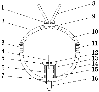
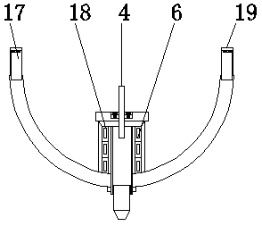
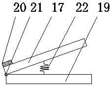
[0015] See Figure 1-3 , An embodiment provided by the present invention: a 3D printer head structure, including a bogie 2, a housing 13 and a fixing frame 14. A base 1 is installed on the bogie 2, and both ends of the top of the base 1 A tie rod 8 is fixed, screw holes 10 are evenly provided on the bogie 2, an adjusting bolt 9 is fixed on one side of the base 1, and the adjusting bolt 9 is connected with the screw hole 10, and both ends...


PUM


Abstract

The invention discloses a 3D printer head structure. The 3D printer head structure comprises a turning rack, a casing and a fixed bracket, wherein a base is mounted on the turning rack; pull rods arefixed at two ends of the top of the base; screw holes are uniformly formed in the turning rack; an adjusting bolt is fixed on one side of the base and connected with the screw holes; fastening blocksare fixed at two ends of the turning rack; clamp slots are uniformly formed in the fastening blocks; the fixed bracket is fixed at the bottom end of the turning rack; connecting blocks are fixed at two ends of the fixed bracket; a heat conducting layer is arranged between a heating cavity and a cylinder; a feeding pipe is mounted at the top end of a piston, and the bottom end of the feeding pipe vertically penetrates through the piston to extend into the cylinder. The turning rack is mounted, and the screw holes are uniformly formed in the turning rack, so that the screw holes and adjusting bolt are connected, the base is fixed on the turning rack, change of the spraying direction of a spray nozzle is realized, and printing of the printer is convenient.

Description

technical field [0001] The invention relates to the technical field of 3D printers, in particular to a 3D printer head structure. Background technique [0002] A 3D printer, also known as a three-dimensional printer, is a digital model file based on the use of special wax, powdered metal or plastic and other bondable materials to manufacture three-dimensional objects by printing layers of adhesive materials. At this stage, three-dimensional Printers are used to manufacture products, and the technology of constructing objects by layer-by-layer printing. The principle of 3D printers is to put data and raw materials into 3D printers, and the machine will build products layer by layer according to the program. At present, 3D printers are common Most of the print heads of 3D printers are fixed, and in order to ensure the printing accuracy of the printed items, the diameter of the spray hole of the nozzle should not be too large, usually 1.75mm. Although this can improve the print...

Claims


Application Information

Patent Timeline
IPC IPC(8): B29C64/20B29C64/209B33Y30/00
CPCB33Y30/00
Inventor 刘庆芳
Owner 刘庆芳
Why Eureka
Try Eureka