Chamfering device for floor packaging boxes

A chamfering device and packaging box technology, applied in the direction of packaging, etc., can solve the problems of high work intensity of employees, affecting the utilization rate of packaging line equipment, low efficiency, etc., and achieve the effect of simple and convenient adjustment, convenient and fast adjustment, and good integration

Pending Publication Date: 2018-02-16
圣象地板(句容)有限公司
View PDF0 Cites 3 Cited by
  • Summary
  • Abstract
  • Description
  • Claims
  • Application Information

AI Technical Summary

Problems solved by technology

At present, hand-held wooden rackets are used to knock the edges and corners of cartons to make them blunt. The artificial blunt corners are irregular in shape, and a large number of long-term knocks cause high work intensity and low efficiency for employees, which affects the equipment utilization of the entire packaging line.

Method used


Image

  • Chamfering device for floor packaging boxes
  • Chamfering device for floor packaging boxes

Examples


Embodiment

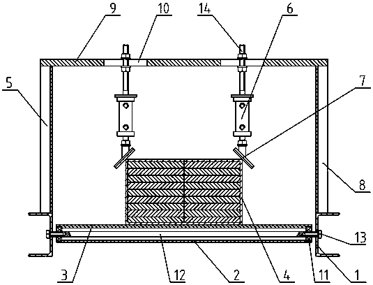
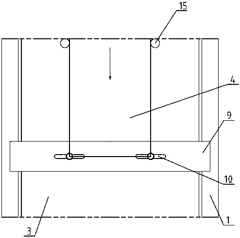
[0018] Such as figure 1 with figure 2 Shown: a chamfering device for floor packaging boxes, including two parallel brackets 1, a number of rollers 2 are arranged between the brackets 1, and a conveyor belt 3 is arranged on the rollers 2, and the conveyor belt 3 is used for Conveying the floor packing box 4, a door-shaped frame 5 is installed on the support 1, two cylinders 6 are installed on the door-shaped frame 5, and a chamfering block 7 is installed on the bottom of the cylinder 6. The chamfering blocks 7 are respectively in contact with the edges and corners on both sides of the top of the floor packing box 4 .

[0019] The gantry frame 5 includes a column 8 and a beam 9 , and the beam 9 is provided with two elongated holes 10 , and the cylinder 6 is installed under the beam 9 through the elongated holes 10 .

[0020] The bottom of the chamfering block 7 is provided with a polyurethane pad. The support 1 is a channel steel, and the drum 2 is equipped with a central sh...


PUM


Abstract

The invention provides a chamfering device for a floor packing box, which comprises two supports arranged in parallel, a number of rollers are arranged between the supports, and a conveyor belt is arranged on the rollers, and the conveyor belt is used to transport the floor packing box. A door-shaped frame is installed on the support, and two cylinders are installed on the door-shaped frame, and chamfering blocks are installed on the bottom of the cylinders, and the two chamfering blocks are respectively connected with the floor packing boxes. The corners on both sides of the top are in contact. The chamfering device of the floor packaging box provided by the present invention has better rigidity and integrity, simple and applicable structure, convenient and quick adjustment, neat and uniform chamfering, which improves the appearance of the company's product packaging, and has good universal adaptability to the frame, and can be adjusted easily. Simple and convenient, the structure meets the mechanical requirements, and overcomes the disadvantages of manual operation.

Description

technical field [0001] The invention relates to a floor packaging box chamfering device, which is used for chamfering packaging boxes on a floor packaging line and belongs to the technical field of floor production equipment. Background technique [0002] After the floor is packed in a corrugated carton, it is necessary to wrap the carton as a whole through a fully automatic film sealing and cutting machine, and finally perform heat shrinking treatment to make the plastic film closely adhere to the surface of the carton. But when the conveyor belt transports the carton forward and drives the film to move together, the two corners at the front of the carton will push the film through. At present, hand-held wooden rackets are used to knock the corners of cartons to make them blunt. The artificial blunt corners are irregular in shape, and a large number of long-term knocks cause high work intensity and low efficiency, which affects the equipment utilization of the entire packag...

Claims


Application Information

Patent Timeline
Patent Type & Authority Applications(China)
IPC IPC(8): B65B61/00
CPCB65B61/00
Inventor 董卫国郑敏戈伟董敏李永红
Owner 圣象地板(句容)有限公司
Why Eureka
Try Eureka