
Waste conveying device with vertical direction conveying function

A vertical direction, transportation device technology, applied in the directions of transportation and packaging, packaging, conveyor objects, etc., can solve the problems of single function, easy congestion of conveyed objects, and complex functions of transportation devices with height difference, and achieve high efficiency. , the effect of increasing diversity

Pending Publication Date: 2018-02-16
成都大运汽车集团有限公司
View PDF4 Cites 0 Cited by
  • Summary
  • Abstract
  • Description
  • Claims
  • Application Information

AI Technical Summary

Problems solved by technology

[0003] The purpose of the present invention is to overcome the disadvantages of the prior art that the conveying device has a single function, the conveying objects are scattered and easily congested at the conveying entrance, and the height difference conveying device has complicated functions, and provides a device combining a micro-compressed horizontal barge and a vertical conveying

Method used


Image

  • Waste conveying device with vertical direction conveying function

Examples


Embodiment Construction

[0010] The present invention will be further described below in conjunction with the accompanying drawings, but the protection scope of the present invention is not limited to the following description.

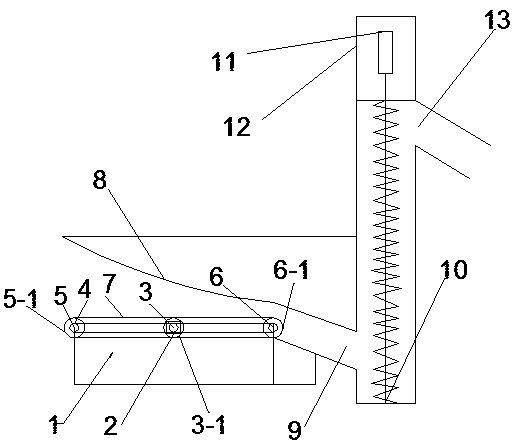
[0011] Such as figure 1 As shown, a garbage transport device with a vertical function includes a body 1, a drive motor 2, a first driving gear 3, a first gear reel 3-1, a conveyor belt 4, a second power gear 5, and a second gear Reel 5-1, third power gear 6, third gear reel 6-1, crawler belt 7, arc-shaped upper cover 8, delivery inlet 9, screw delivery rod 10, motor 11, motor housing 12, delivery outlet 13, The body 1 is an integral structure, which is divided into two functional parts: horizontal transportation and vertical transportation. The driving motor 2 is fixed on the horizontal part of the body 1. The first driving gear 3 is concentrically connected with the driving motor 2 and is set on the driving motor 2. Above, the driving motor drives the driving gear 3 to rota...


PUM


Abstract

The invention relates to the field of waste conveying, and provides a micro compression type horizontal transferring and vertical conveying combined device to overcome the defects that a conveying device in the prior art is monotonous in function, conveyed goods are scattered and block a conveying inlet easily, and a height difference conveying device has complex functions. Waste is placed througha left end caterpillar band of the horizontal part, a driving motor drives a first driving gear to rotate and then drives all driving gears to rotate, and all the driving gears drive all gear drums to rotate respectively and then drive the caterpillar band to move finally. Then, the caterpillar band drives waste to be horizontally conveyed rightwards, and the waste finally enters a conveying inlet under the extrusion effect of an arc upper cover, a motor drives an auger delivery rod to rotate, the waste rises along the delivery rod during motion of the delivery rod and is conveyed out from aconveying outlet when reaching the top, and waste conveying is more efficient.

Description

technical field [0001] The invention relates to the field of material transportation, in particular to a garbage transportation device with a vertical transportation function. Background technique [0002] With the rapid development of social urbanization, more and more attention has been paid to the disposal of urban waste, and the disposal and transportation of waste is also a relatively major problem. At present, most cities use human sanitation workers and garbage trucks to deal with waste, and the human resources invested are relatively small. Considering the pan-automation of this kind of garbage disposal work in the future, the transportation and treatment of garbage needs to be realized in an automated and multi-functional way. And most of the existing technologies are garbage disposal, while the transportation of garbage usually adopts manual mode, or traditional simple one-way transportation device, which is easy to cause congestion when too much garbage is accumul...

Claims


Application Information

Patent Timeline
Patent Type & Authority Applications(China)
IPC IPC(8): B65G33/14B65G33/24B65G47/34
CPCB65G33/14B65G33/24B65G47/34
Inventor 唐磊严凯
Owner 成都大运汽车集团有限公司
Learn More