Supercharge Your Innovation With Domain-Expert AI Agents!

Textile cloth winding device capable of achieving switchable application

A technology of cloth rolling, left and right sides, applied in the field of textile rolling devices, can solve the problems that affect the rolling process, cannot meet the needs of mass production, and low efficiency, and achieve the effect of improving the production efficiency of enterprises and improving the work efficiency of cloth rolling

Inactive Publication Date: 2018-02-16
方安定
View PDF5 Cites 0 Cited by
  • Summary
  • Abstract
  • Description
  • Claims
  • Application Information

AI Technical Summary

Problems solved by technology

Then it is necessary to remove the rolled fabric from the cloth roll. The process of unloading the tubular fabric is more complicated, and then replace the new cloth stick to rewind, and then start the next round of winding. This method is more efficient. Low, complex structure, cumbersome operation, cannot meet the needs of mass production, and requires more manpower and time, the cloth winding efficiency is low, affecting the overall cloth rolling process, reducing the profit of the enterprise

Method used


Image

  • Textile cloth winding device capable of achieving switchable application
  • Textile cloth winding device capable of achieving switchable application
  • Textile cloth winding device capable of achieving switchable application

Examples


Embodiment Construction

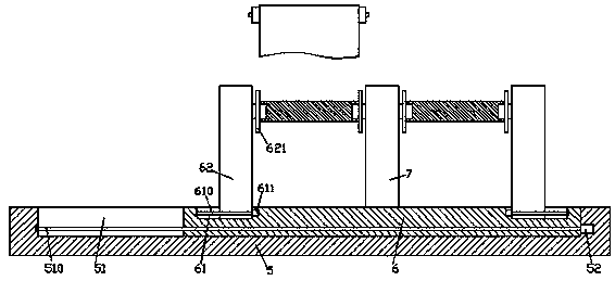
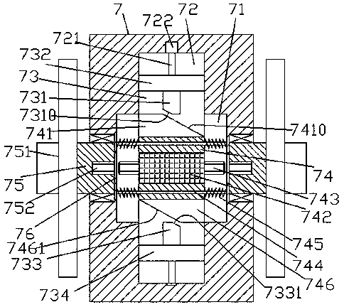
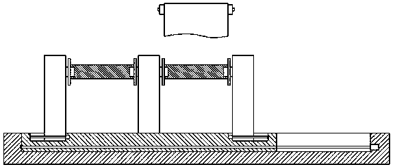
[0024] Such as Figure 1-Figure 5 As shown, a switchable textile cloth rolling device of the present invention includes a base 5 and a movable base 6 installed in the base 5, and the top end faces of the left and right sides of the movable base 6 are internally symmetrical. There are guide grooves 61, each of the guide grooves 61 is provided with a second threaded rod 610 extending from left to right, and the middle position of the top end surface of the moving bottom bracket 6 is fixed with a first support frame 7 extending upward, The left and right sides of the first support frame 7 are symmetrically provided with a second support frame 62 extending up and down. It is threadedly connected with the second threaded rod 610 in the guide groove 61 on the left and right sides, and the second support frame 62 on the left and right sides is connected to the opposite side of the top extension section of the first support frame 7 by rotation. The first locking member 621, the left ...


PUM


Abstract

The invention discloses a textile cloth winding device capable of achieving switchable application. The textile cloth winding device comprises a base and a movable collet mounted in the base. Guidinggrooves are symmetrically formed in the end faces of the tops of the left side and the right side of the movable collet. A second threaded rod extending left and right is arranged in each guiding groove. A first supporting frame extending upwards is fixedly arranged in the middle of the end face of the top of the movable collet. Second supporting frames extending up and down are symmetrically arranged on the left side and the right side of the first supporting frame. The bottom extension end of the second supporting frame on the left side and the bottom extension end of the second supporting frame on the right side extend into the left guiding groove and the right guiding groove correspondingly and are connected with the second threaded rods in the guiding grooves in the left side and theright side in a threaded fit mode correspondingly. The opposite side of the extension section of the top of the second supporting frame on the left side, the opposite side of the extension section ofthe top of the second supporting frame on the right side and the opposite sides of the extension sections of the top of the first supporting frame are connected with first clamping locking parts in arotating fit mode correspondingly. The textile cloth winding device is simple in structure and convenient to operate, investment input is reduced, the purchase cost is reduced, and the working efficiency and the whole cloth winding progress are improved.

Description

technical field [0001] The invention relates to the technical field of weaving, in particular to a weaving fabric rolling device which can be switched and used. Background technique [0002] After the cloth tape has been weaved, dyed and other processes, the cloth tape needs to be rolled up so that the rolled cloth tape is convenient for packaging and transportation. The cloth take-up shaft on the support frame, the cloth take-up roller sleeved on the cloth take-up shaft and the motor that drives the cloth take-up shaft to rotate; when taking up the cloth, first fix one end of the cloth on the cloth take-up roller, turn on the motor, and roll the cloth close action. Then it is necessary to remove the rolled fabric from the cloth roll. The process of unloading the tubular fabric is more complicated, and then replace the new cloth stick to rewind, and then start the next round of winding. This method is more efficient. The structure is relatively low, the structure is comple...

Claims


Application Information

Patent Timeline
IPC IPC(8): B65H18/02B65H18/10B65H19/22
CPCB65H18/02B65H18/021B65H18/028B65H18/10B65H19/2269B65H19/2292B65H2402/40B65H2403/55B65H2403/90
Inventor 方安定姚莉萍
Owner 方安定
Features
  • R&D
  • Intellectual Property
  • Life Sciences
  • Materials
  • Tech Scout
  • Unparalleled Data Quality
  • Higher Quality Content
  • 60% Fewer Hallucinations
Learn More