Cloth winding device with automatic adjusting function

An automatic adjustment and functional technology, applied in the direction of winding strips, transportation and packaging, thin material processing, etc., can solve the problems of affecting the efficiency of cloth rolling, power consumption, and affecting work efficiency, so as to improve the movement stability and improve the volume Cloth stability, the effect of improving work efficiency

Inactive Publication Date: 2018-02-16
吴康康
View PDF8 Cites 0 Cited by
  • Summary
  • Abstract
  • Description
  • Claims
  • Application Information

AI Technical Summary

Problems solved by technology

There is still a certain distance between the cloth conveyed by the conveying roller and the cloth take-up roller. If the cloth is not supported during this period, the cloth will easily sag under its own gravity, and the winding of the cloth take-up roller will be affected during the drooping process. resistance, which affects the efficiency of cloth rolling, and the cloth is wound under the pulling of the cloth rolling roller, which is easy to damage the cloth, thereby affecting the quality of winding. In addition, the position of the cloth guide roller of the existing cloth winding machine is fixed, and it is uniform for thick and thin cloth. One kind of winding spacing is adopted. If the spacing is too large, it will easily lead to irregular winding of the fabric. It is necessary to stop the winding in time and tighten the fabric before rewinding, which greatly affects the work efficiency, and the excessive spacing requires rollers. Provides greater pulling force and consumes more power

Method used


Image

  • Cloth winding device with automatic adjusting function
  • Cloth winding device with automatic adjusting function
  • Cloth winding device with automatic adjusting function

Examples


Embodiment Construction

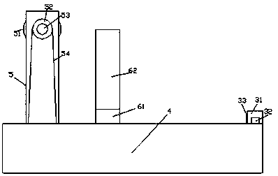
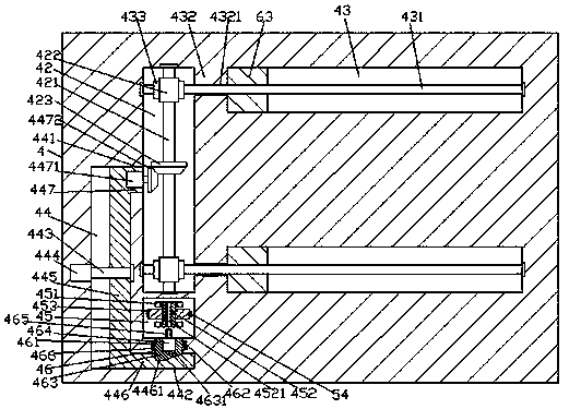
[0023] Such as Figure 1-Figure 5 As shown, a cloth rolling device with automatic adjustment function of the present invention includes a base 4 and a cloth rolling frame 5 fixed on the top end surface of the left side of the base 4, and the inside of the left side of the base 4 is provided with a The first cavity 42, the base 4 on the right side of the first cavity 42 is provided with a guide groove 43 that is symmetrical up and down and extends left and right, and the left end of each guide groove 43 is connected to the first cavity. A partition 432 is provided between the right ends of the body 42, each of the partitions 432 is provided with a through hole 4321, and each of the through holes 4321 is transitionally fitted with a second wall extending to the left and right sides. A threaded rod 431, the left side extension end of the first threaded rod 431 extends into the first cavity 42 and is connected with the left inner wall of the first cavity 42 in a rotational fit, th...


PUM


Abstract

The invention discloses a cloth winding device with an automatic adjusting function. The cloth winding device comprises a base and a cloth winding frame fixed to the end face of the top of the left side of the base. A first cavity extending front and back is formed in the left side of the base, and the part, on the right side of the first cavity, of the base is internally provided with guiding grooves which are symmetric up and down and extend left and right. A partition plate is arranged between the tail end of the left side of each guiding groove and the right side end of the first cavity. Each partition plate is internally provided with a penetration hole. Each penetration hole is internally provided with a first threaded rod in a transition fit manner, wherein the first threaded rod extends towards the left side and the right side. The extending tail end of the left side of each first threaded rod stretches into the first cavity and is connected with the inner wall of the left sideof the first cavity in a rotation fit manner, and the extending tail ends of the right sides of the first threaded rods stretch into the guiding grooves and are connected with the inner walls of theright sides of the guiding grooves in a rotation fit manner. The cloth winding device is simple in structure, the winding quality of wound cloth is improved, the cloth winding efficiency is improved,the cloth winding tidiness is achieved, the surface of the cloth of the wound cloth roll is flat, and wrinkling is avoided.

Description

technical field [0001] The invention relates to the technical field of textile processing machinery, in particular to a cloth rolling device with an automatic adjustment function. Background technique [0002] In the weaving process, after the weaving machine finishes weaving, the cloth must be pulled to a preset cloth winding machine, and the cloth winding machine will wind the cloth onto a cloth roller for transportation and storage. There is still a certain distance between the cloth conveyed by the conveying roller and the cloth take-up roller. If the cloth is not supported during this period, the cloth will easily sag under its own gravity, and the winding of the cloth take-up roller will be affected during the drooping process. resistance, which affects the efficiency of cloth rolling, and the cloth is wound under the pulling of the cloth rolling roller, which is easy to damage the cloth, thereby affecting the quality of winding. In addition, the position of the cloth ...

Claims


Application Information

Patent Timeline
Patent Type & Authority Applications(China)
IPC IPC(8): B65H18/10B65H23/16
CPCB65H18/10B65H23/16B65H2701/174
Inventor 吴康康王益忠
Owner 吴康康
Why Eureka
Try Eureka