Industrial wastewater nanofiltration separation system

A technology for separation system and industrial sewage, which is applied in semi-permeable membrane separation, water/sewage treatment, water/sludge/sewage treatment, etc. It can solve the problem of adjusting water output rate, affecting sewage treatment efficiency, and poor water flow through nanofiltration membranes. and other issues, to achieve the effect of improving the use effect, increasing the use width, and guaranteeing the water outlet efficiency

Pending Publication Date: 2018-02-16
宜兴市中发水处理环保设备有限公司
View PDF3 Cites 0 Cited by
  • Summary
  • Abstract
  • Description
  • Claims
  • Application Information

AI Technical Summary

Problems solved by technology

[0002] In the existing nanofiltration treatment of industrial sewage, due to the limited treatment efficiency of a single nanofiltration treatment device for sewage, it is impossible to adjust the water output rate according to the actual needs of the process, and cannot meet the standard requirements of different processes. In addition, the nanofiltration treatment device The nanofiltration membrane is also very easy to be accumulated by some impurities in the sewage, resulting in poor water flow. Once this happens, the staff have to stop the machine to clean the nanofiltration membrane, which seriously affects the overall treatment efficiency of sewage

Method used


Image

  • Industrial wastewater nanofiltration separation system

Examples


Embodiment 1

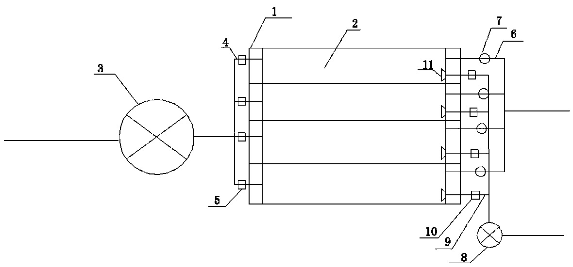
[0014] Such as figure 1 As shown, the present invention provides a nanofiltration separation system for industrial sewage, including a nanofiltration box 1 and an inlet pump 3. The nanofiltration box 1 is provided with four nanofiltration devices 2, and the nanofiltration devices 2 are respectively provided with The inlet pipe 4 and the outlet pipe 6, the inlet pipe 4 is connected to the inlet pump 3, the inlet pipe 4 is provided with an inlet valve 5, the outlet pipe 6 is provided with a flow meter 7, the nanofiltration device 2 There is also a cleaning pipe 9 connected to the cleaning pump 8, the cleaning pipe 9 is provided with a cleaning valve 10, and the inner wall of the nanofiltration device 2 is provided with a shower connected to the cleaning pipe 9 Head 11.

Embodiment 2

[0016] According to the process requirements of sewage treatment, 3 nanofiltration devices 2 are required to be put into use at the same time. Open 3 of the 4 water inlet valves 5, and the water inlet pump 3 pumps industrial wastewater into these 3 nanofiltration devices 2 for nanofiltration. For processing, the staff observes the corresponding flow meters 7 on the water outlet pipes 6 of the three nanofiltration devices 2. Once it is found that the water output rate of one of the flow meters 7 is significantly lower than that of the other two, it is determined that the nanofiltration device 2 When a blockage occurs, the staff closes the water inlet valve 5 of the nanofiltration device 2 and opens its cleaning valve 10 at the same time. The cleaning pump 8 flushes the clean water through the spray head 11 to the nanofiltration device 2 and opens the other An unused water inlet valve 5 of the nanofiltration device 2 is put into use, so that in the process of cleaning the clogged ...


PUM


Abstract

The invention discloses an industrial wastewater nanofiltration separation system. The industrial wastewater nanofiltration separation system comprises a nanofiltration tank and a water inlet pump, wherein at least two nanofiltration devices are arranged in the nanofiltration tank, each nanofiltration device is provided with a water inlet pipe and a water outlet pipe, each water inlet pipe is connected with the water inlet pump, each water inlet pipe is provided with a water inlet valve, a flow meter is arranged on each water outlet pipe, a cleaning pipe is also arranged on each nanofiltrationdevice, each cleaning pipe is connected with a cleaning pump, and a cleaning valve is arranged on each cleaning pipe. The industrial wastewater nanofiltration separation system disclosed by the invention has the advantages that quantity of the nanofiltration devices put into use can be specifically selected according to the actual requirement of technology, so that the technological requirement of multiple water output rates can be met, usage width of the system is increased, and using effect is improved.

Description

Technical field [0001] The invention relates to the technical field of sewage treatment, in particular to a nanofiltration separation system for industrial sewage. Background technique [0002] Existing industrial sewage nanofiltration treatment, due to the limited efficiency of a single nanofiltration treatment device for sewage treatment, it is impossible to adjust the water outlet rate according to the actual needs of the process, and cannot meet the standard requirements of different processes. In addition, in the nanofiltration treatment device The nanofiltration membrane is also very easy to be accumulated by some impurities in the sewage, and the water is not smooth. Once this happens, the staff has to stop the machine to clean the nanofiltration membrane, which seriously affects the overall sewage treatment efficiency. Summary of the invention [0003] Objective of the invention: In order to overcome the deficiencies in the prior art, to provide a nanofiltration separation...

Claims


Application Information

Patent Timeline
Patent Type & Authority Applications(China)
IPC IPC(8): C02F1/44B01D61/02B01D61/08B01D65/02
CPCB01D61/08B01D65/02C02F1/442C02F2301/08C02F2303/14B01D61/026
Inventor 陈立中张志鹏刘文俊陈皓
Owner 宜兴市中发水处理环保设备有限公司
Why Eureka
Try Eureka