
Ring-shaped light guide plate

A technology of light guide plate and circular ring, applied in the direction of light guide, optics, optical components, etc., can solve the problems of reducing the brightness of light output, waste of resources, light loss, etc., and achieve the effect of expanding the output angle, rational use, and reducing light loss

Inactive Publication Date: 2018-02-16
PHICOMM (SHANGHAI) CO LTD
View PDF9 Cites 1 Cited by
  • Summary
  • Abstract
  • Description
  • Claims
  • Application Information

AI Technical Summary

Problems solved by technology

[0003] In order to solve this kind of problem, the current common practice is to add astigmatism powder into the light guide plate, so that the light emitted by the LED diverges in all directions to form a uniform light guide effect. Loss, reduce the brightness of the light output, and then require a higher power light source, resulting in a waste of resources

Method used

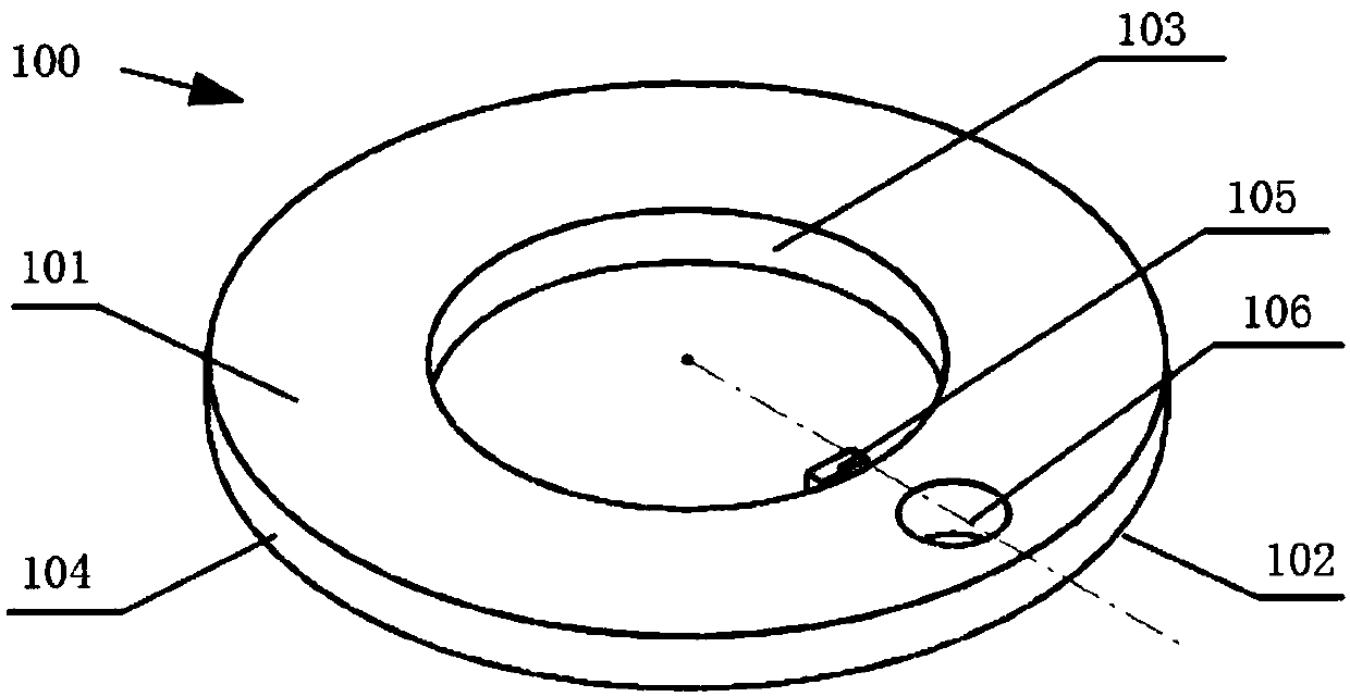
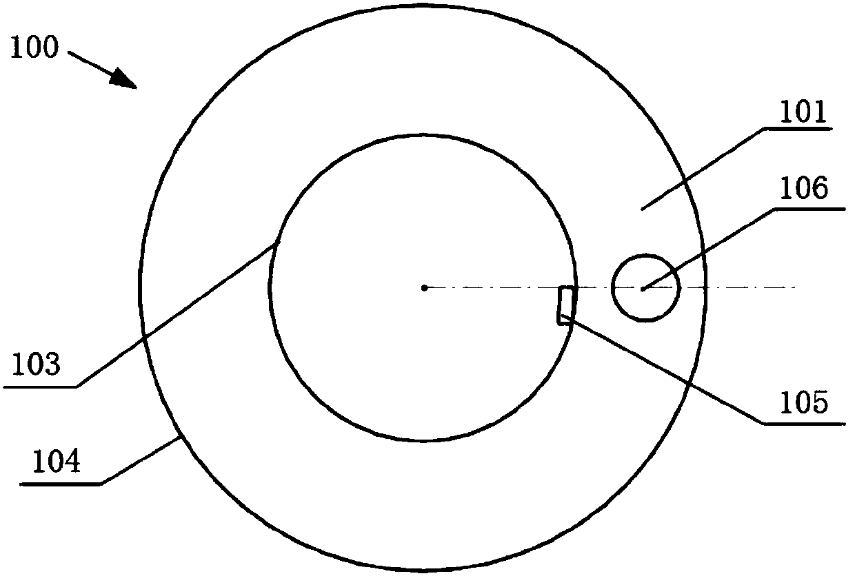
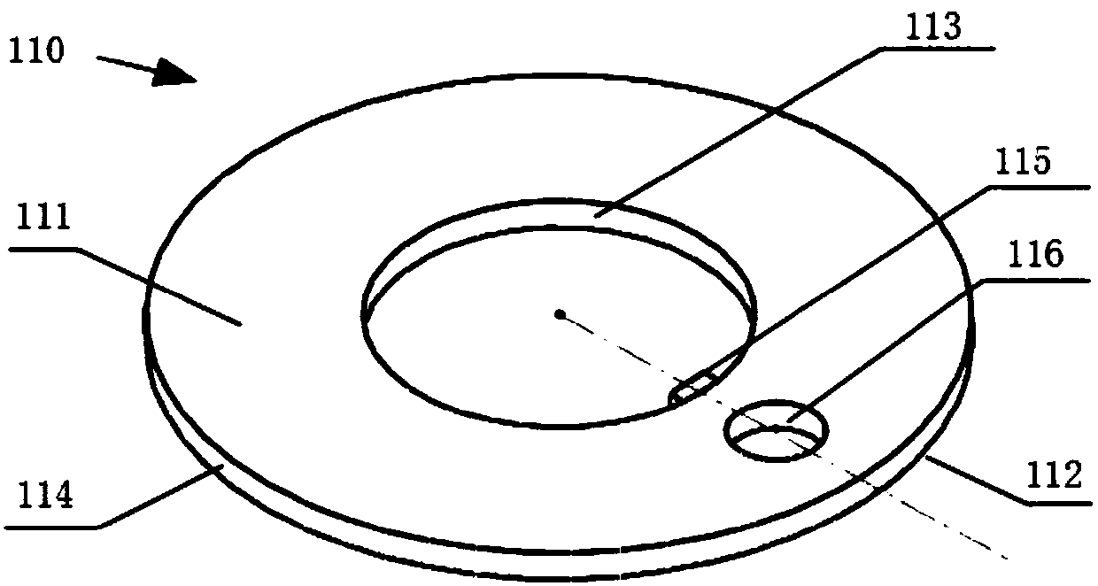

Image

  • Ring-shaped light guide plate
  • Ring-shaped light guide plate
  • Ring-shaped light guide plate

Examples


Embodiment Construction

[0021] In order to enable those skilled in the art to better understand the technical solutions of the present invention, the following will clearly and completely describe the technical solutions in the embodiments of the present invention in conjunction with the accompanying drawings of the embodiments of the present invention. Obviously, the described embodiments It is only a part of the embodiments of the present invention, but not all of them.

[0022] It should be noted that when an element is expressed as being "fixed to" another element, it may be directly on the other element, or there may be one or more intervening elements therebetween. When an element is referred to as being "connected to" another element, it can be directly connected to the other element or one or more intervening elements may be present therebetween. The terms "perpendicular", "parallel", "left", "right" and similar expressions are used in this specification for the purpose of description only. ...


PUM


Abstract

The present invention provides a ring-shaped light guide plate comprising an upper surface, a lower surface, an inner wall of an inner periphery of a ring, and an outer wall of an outer periphery of the ring. An incident surface of the ring-shaped light guide plate is formed by the inner wall; and a light-emitting surface of the ring-shaped light guide plate is formed by the outer wall. At least one LED is arranged on the inner wall. At least one circular through hole is formed in the ring-shaped light guide plate; the circular through hole is formed in a light-emitting path direction of the LED and at least one part of light emitted by the LED passes through the circular through hole and then is refracted. Therefore, a problem that non-uniform brightness of different regions on a light strip is caused when an interrupted point light source is employed is solved, so that emitted light becomes uniform. Meanwhile, when light is transmitted in the light guide plate, light losses are reduced because no other absorbing media exist and thus the luminous efficiency is improved, so that energy saving and environmental protection effects are realized, the uniform luminance of emitted lightis high, and the light guide plate resources are utilized reasonably.

Description

technical field [0001] The invention relates to the field of display technology, in particular to an annular light guide plate. Background technique [0002] The light guide plate is a commonly used part in electronic products. The light guide plate is usually a transparent PC (polycarbonate) or acrylic material. Its function is to transmit the light emitted by the LED to the appearance of the product, indicating the working status of the product and beautifying the appearance. . LEDs are usually in a square structure and are soldered on the PCB. Due to the relatively small size of the LED, the range of light it emits is limited. Usually, a combination of several LEDs is arranged to provide a light source for a light guide plate, thereby forming a ring or strip light strip, which poses a problem. Due to the use of intermittent For point light sources, different areas on the light strip have different brightness and darkness, which greatly reduces the appearance of the prod...

Claims


Application Information

Patent Timeline
Patent Type & Authority Applications(China)
IPC IPC(8): G02B6/00
CPCG02B6/0033G02B6/0036G02B6/0055G02B6/0065G02B6/0091
Inventor 黄博林
Owner PHICOMM (SHANGHAI) CO LTD
Learn More