
Antenna device

An antenna device and chip antenna technology, applied in directions such as antenna, antenna support/installation device, antenna coupling, etc., can solve problems such as damage to the electronic device of the antenna device, the metal shell of the antenna device being charged, and the use time being too long.

Active Publication Date: 2018-02-16
SHENZHEN SHENGLU IOT COMM TECH CO LTD
View PDF8 Cites 3 Cited by
  • Summary
  • Abstract
  • Description
  • Claims
  • Application Information

AI Technical Summary

Problems solved by technology

[0004] Due to the single electrical connection of data wires in the existing antenna device, when level fluctuations occur on the chip antenna or the carrier board, it cannot better maintain the stability of the antenna signal transmission in the antenna chip and the carrier board This reduces the transmission efficiency of the antenna signal, and when the existing antenna device is used for too long or damaged, the insulation performance will be reduced, and the metal shell of the antenna device will be charged, which will easily cause the antenna device to be damaged. The damage of the electronic devices inside further reduces the transmission efficiency of the antenna signal

Method used


Image

  • Antenna device
  • Antenna device
  • Antenna device

Examples


Embodiment Construction

[0043] In order to facilitate the understanding of the present invention, the present invention will be described more fully below with reference to the associated drawings. Several embodiments of the invention are shown in the drawings. However, the present invention can be embodied in many different forms and is not limited to the embodiments described herein. Rather, these embodiments are provided so that the disclosure of the present invention will be thorough and complete.

[0044] It should be noted that when an element is referred to as being “fixed on” another element, it may be directly on the other element or there may be an intervening element. When an element is referred to as being "connected to" another element, it can be directly connected to the other element or intervening elements may also be present. The terms "vertical," "horizontal," "left," "right," and similar expressions are used herein for purposes of illustration only.

[0045] Unless otherwise def...


PUM


Abstract

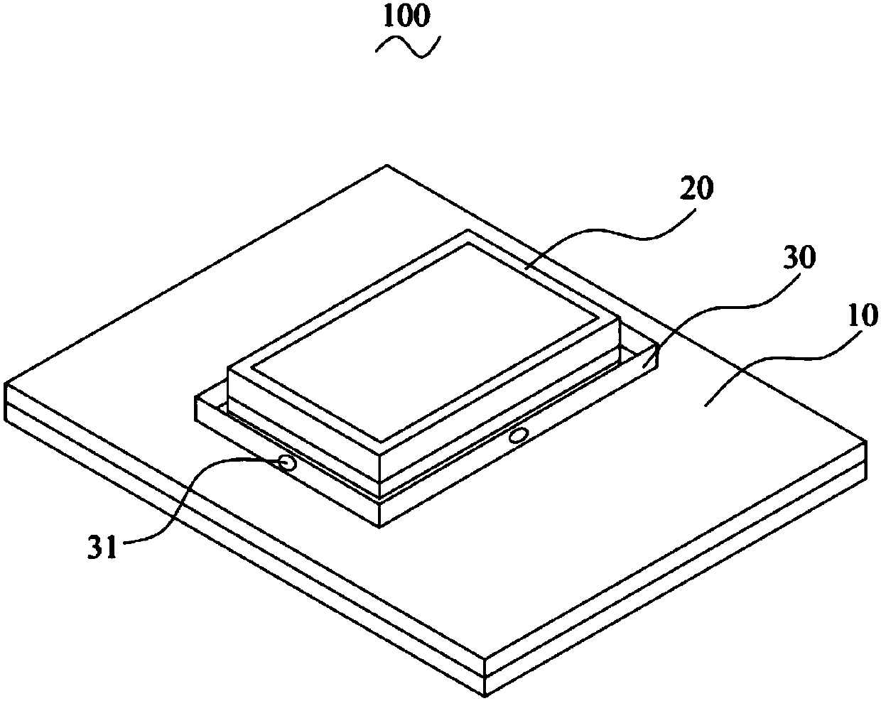
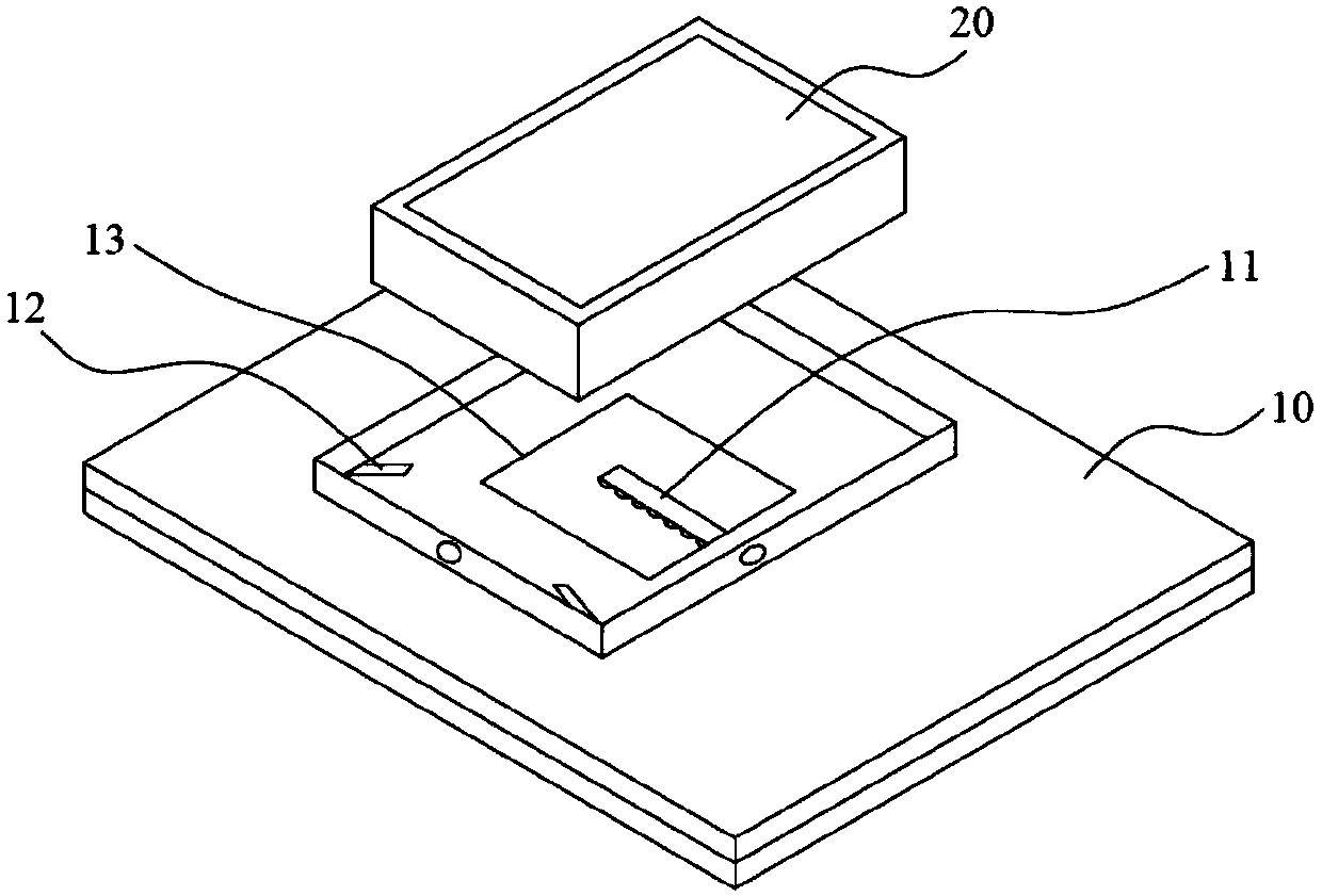
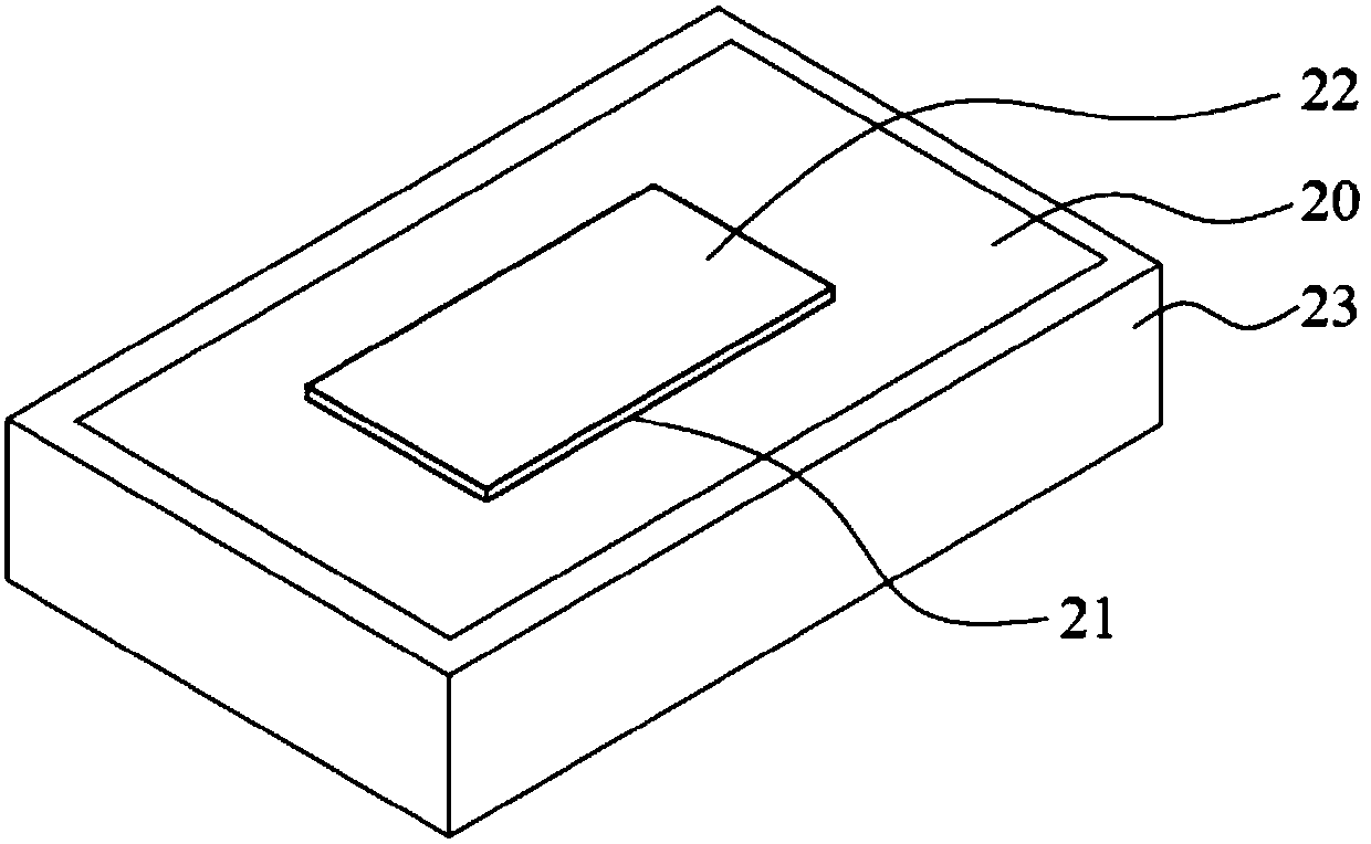
An antenna device includes a bearing plate and a chip antenna. The bearing plate is internally provided with a coupling adjustment component and a signal transmission conductor. The coupling adjustment component includes ground plates and coupling conductors. The ground plates are arranged in the corners of the bearing plate. The coupling conductors are electrically connected with the chip antenna. The signal transmission conductor includes a transmission plate and bulges. The bearing plate is provided with a limiting part and a connecting hole on the side facing the chip antenna. The chip antenna is arranged in the limiting part. The limiting part is provided with a positioning through hole. The chip antenna is internally provided with an emitting conductor unit which is electrically connected with the transmission plate. Through the design of the coupling adjustment component, the coupling in the antenna device can be adjusted, level fluctuation caused by too large or too small coupling is prevented, and the signal transmission efficiency of the antenna device is improved. Through the design of the ground plates, the leakage phenomenon of the shell of the chip antenna due to thedegradation of the insulation performance is prevented, and the signal transmission efficiency of the antenna device is improved.

Description

technical field [0001] The present invention relates to the technical field of antennas, in particular to an antenna device. Background technique [0002] In recent years, all kinds of wireless communication devices, such as smart phones, tablet computers, personal wireless navigation, portable players, etc., have integrated all current communication functions into the device, and the antenna device is used to The components for sending and receiving radio signals are undoubtedly one of the most important components in wireless communication devices. Antenna devices are widely loved by people for their small size, stable signal transmission, and strong anti-interference ability. With the rapid development, people have higher and higher requirements on the signal transmission efficiency of the antenna device. [0003] The existing antenna device includes an antenna chip and a carrier board electrically connected to the antenna chip. The antenna chip and the carrier board are...

Claims


Application Information

Patent Timeline
IPC IPC(8): H01Q1/12H01Q1/50H01Q1/52
CPCH01Q1/125H01Q1/50H01Q1/526
Inventor 杜光东
Owner SHENZHEN SHENGLU IOT COMM TECH CO LTD
Learn More