Load state control method and system
A technology of load state and control method, applied in the field of cloud platform, can solve the problem of not being able to control the load state of cloud hosts
- Summary
- Abstract
- Description
- Claims
- Application Information
AI Technical Summary
Problems solved by technology
Method used
Image
Examples
Embodiment 1
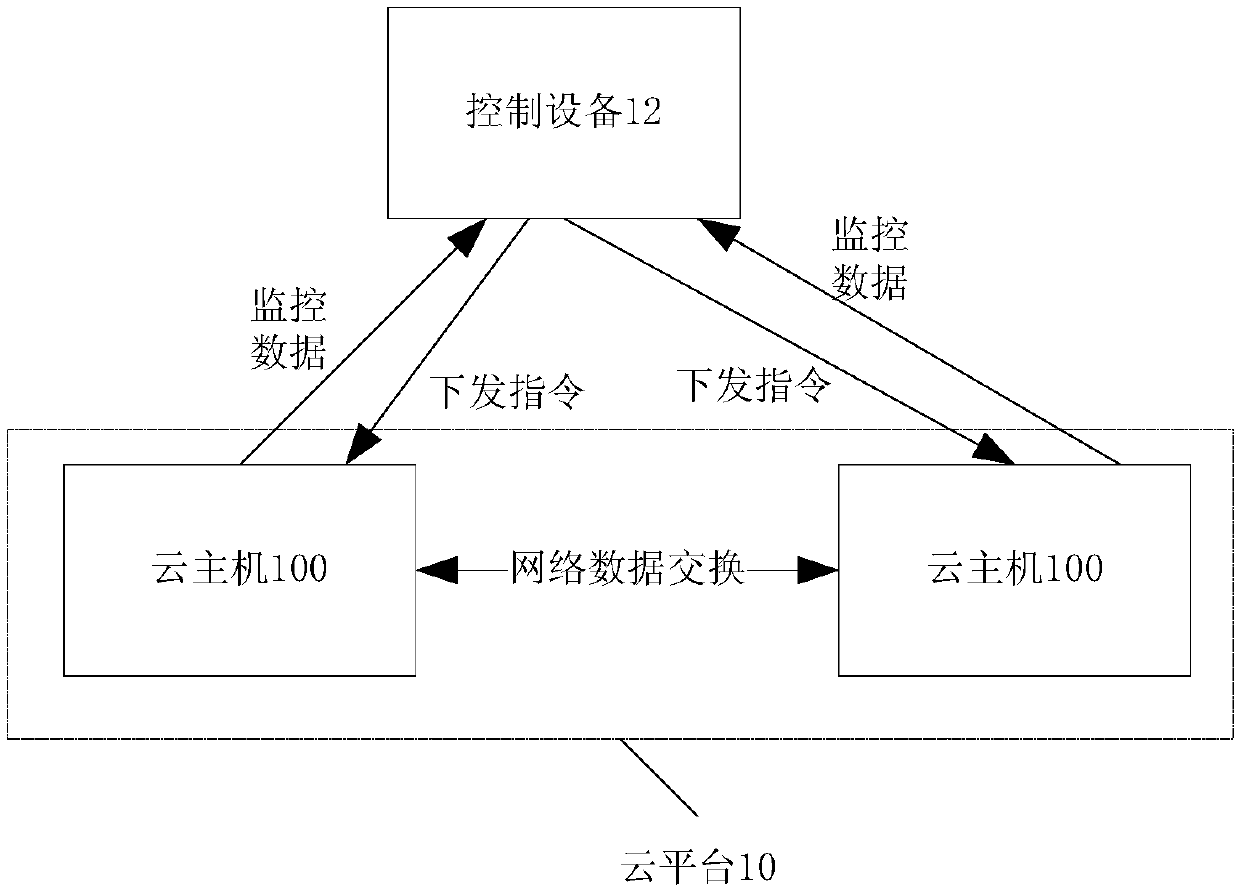
[0030] Such as figure 1 As shown, the system includes: a cloud platform 10 , a cloud host 100 , and a control device 12 . in:
[0031] The control device 12 controls each proxy node and monitors the resource load of each control device cloud host 100 in real time, and then the proxy node provides the current operation status and cloud host resource consumption to the control device 12 in real time according to the instructions. The control device configuration should make each cloud host 100 The load status maintained by the host 100, when the load does not meet the requirements, sends an instruction to the agent node, and the agent node receives the instruction sent by the control device and adjusts the execution speed of the program accordingly, so that the resource consumption of the cloud host is maintained at the configured load value. Wherein, the control device 12 has a WEB interface for realizing human-computer interaction.
[0032] Based on the above application sce...
Embodiment 2
[0051] According to an embodiment of the present invention, an embodiment of a load state control method is provided. It should be noted that the steps shown in the flowcharts of the accompanying drawings can be executed in a computer system such as a set of computer-executable instructions, and , although a logical order is shown in the flowcharts, in some cases the steps shown or described may be performed in an order different from that shown or described herein.
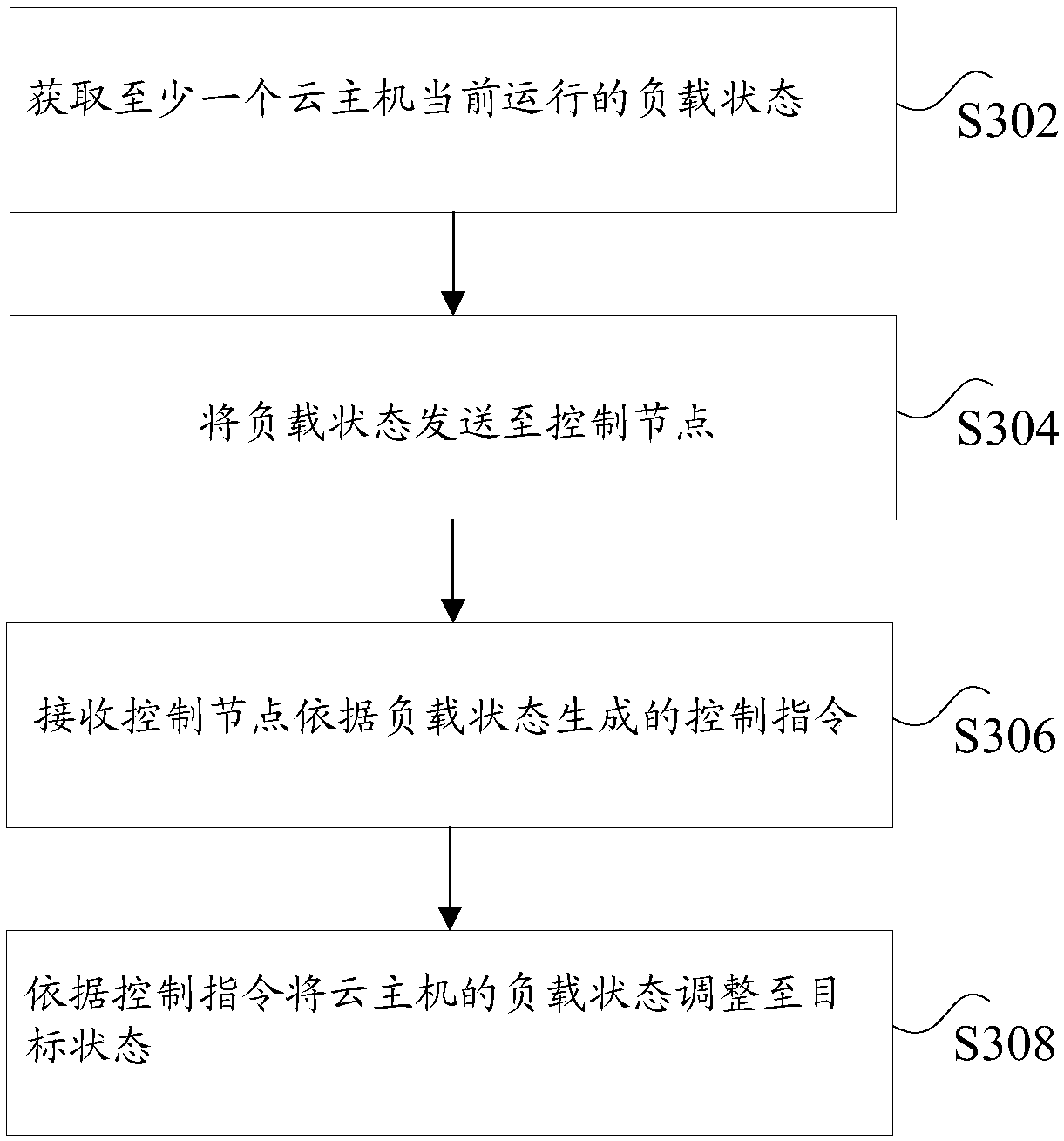
[0052] image 3 is a load state control method according to an embodiment of the present invention, such as image 3 As shown, the method includes the following steps:
[0053] Step S302, obtaining the load status of at least one cloud host currently running.
[0054] Optionally, before obtaining the load status of at least one cloud host currently running, obtain a list of cloud hosts with proxy functions in the network where at least one cloud host is located, wherein the proxy function is used to realize the...
Embodiment 3
[0066] An embodiment of the present invention provides an embodiment of a load state control system. Figure 4 is a structural diagram of a load state control system according to an embodiment of the present application. Such as Figure 4 As shown, the control system of this load state includes:
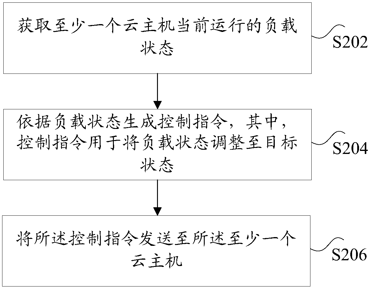
[0067] The control device 40 is used to obtain the load status of at least one cloud host currently running; generate a control command according to the load status; send the control command to at least one cloud host;
[0068] At least one cloud host 42 in the cloud platform is used to receive the control instruction and adjust the load state to the target state according to the control instruction.
[0069] It should be noted that, for a preferred implementation manner of this embodiment, reference may be made to relevant descriptions in Embodiment 1 or 2, and details are not repeated here.
PUM
 Abstract
Description
Claims
Application Information
 - R&D
- Intellectual Property
- Life Sciences
- Materials
- Tech Scout
- Unparalleled Data Quality
- Higher Quality Content
- 60% Fewer Hallucinations
Browse by: Latest US Patents, China's latest patents, Technical Efficacy Thesaurus, Application Domain, Technology Topic, Popular Technical Reports.
© 2025 PatSnap. All rights reserved.Legal|Privacy policy|Modern Slavery Act Transparency Statement|Sitemap|About US| Contact US: help@patsnap.com


