Tooth observer

An observer and tooth technology, applied in the field of dental observers, can solve the problems of inconvenient operation, unstable shooting and the like, and achieve the effect of easy operation

Inactive Publication Date: 2018-02-23
长春光速科技有限公司
View PDF4 Cites 6 Cited by
  • Summary
  • Abstract
  • Description
  • Claims
  • Application Information

AI Technical Summary

Problems solved by technology

[0006] In order to solve the problems of unstable shooting and inconvenient operation of the hand-held tooth observation and detection device in the prior art, the present invention provides a tooth viewer with a rotatable camera device and a bracket

Method used


Image

  • Tooth observer
  • Tooth observer
  • Tooth observer

Examples


specific Embodiment approach 1

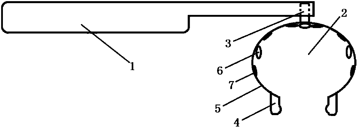
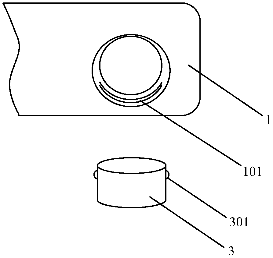
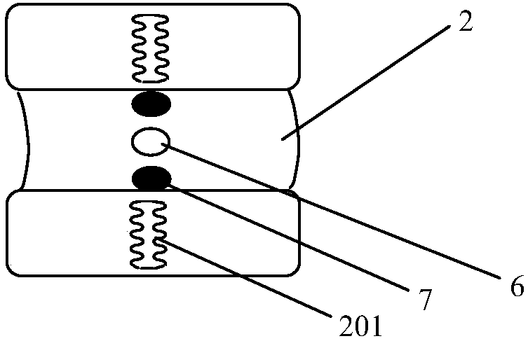
[0030] The tooth viewer includes: a handle 1, a camera device 2, a connecting shaft 3, a support frame 4 and a control unit, such as figure 1 shown. The camera device 2 includes a fixed frame 5 , a camera 6 and a luminous body 7 . One end of the handle 1 is connected to the camera 2 through the connecting shaft 3, the support frame 4 is arranged at the opening of the camera 2, the camera 6 and the luminous body 7 are located on the fixed frame 5, and the camera 6 and the luminous body 7 are electrically connected to the control unit.

[0031] The imaging device 2 and the handle 1 can realize relative rotation, and realize self-adaptive relative rotation in the oral cavity. The illuminant 7 can simultaneously illuminate the upper surface, the inner surface and the outer surface of the tooth to be photographed. When the illuminant 7 illuminates the tooth to be photographed, the tooth to be photographed will not produce an obvious umbra, which achieves the effect of a shadowless...

specific Embodiment approach 2

[0040] The difference from the first embodiment is that, if Figure 5 Shown, also comprise blower 9, blowing pipe 10, liquid receiving box 11, puller 12, suction pipe 13, main switch 14 and photographing switch 15. One end of the blowing pipe 10 is connected to the blower 9, and the other end passes through the middle part of the fixed frame 5. The blower 9 is energized and works to generate warm air (the temperature is similar to the oral cavity temperature, such as 37° C.), and is blown through the blowing pipe 10 to the teeth to be photographed. surface. The liquid receiving box 11 is arranged on the handle 1, the pump 12 is arranged in the liquid receiving box 11, one end of the suction pipe 13 is located on the side of the support frame 4, and the other end is connected to the liquid receiving box 12; The saliva near the shooting area in the oral cavity is introduced into the liquid receiving box 11 through the water suction tube 13 . The liquid receiving box 11 can be ...


PUM


Abstract

The invention provides a tooth observer, and relates to the field of tooth examination, which solves the problems of inconvenience in shooting and instability in shooting in the prior art. The tooth observer comprises a handle, a shooting device, a connecting shaft, a support frame and a control unit, wherein the shooting device comprises a fixed frame, a camera and a light emitting body; one endof the handle is connected with the shooting device through the connecting shaft, and the shooting device can be rotated relative to the handle; the support frame is arranged at an opening of the shooting device, and the support frame is arranged at the inside and outside of gingival to support the shooting device; the camera and the light emitting body are positioned on the fixed frame, and the light emitting body is used for simultaneously illuminating the upper surface, inside surface and outside surface of a tooth; the control unit is electrically connected with the camera and the light emitting body, and is used for controlling the shooting of the camera and the light emitting of the light emitting body. The tooth observer has the advantages that the shooting device can be rotated relative to the handle in an oral cavity in a self-adaptive way, and the operation is simple and convenient; the support frame is used for supporting the shooting device via the gingival, so that the stable image or video can be quickly obtained; the tooth observer is suitable for being applied to tooth examination in home and dental hospitals.

Description

technical field [0001] The invention relates to the field of tooth detection, in particular to a tooth viewer. Background technique [0002] As people's awareness of tooth protection gradually rises, in daily life, people need to observe their teeth frequently to see if there are any problems. For example, observe the brightness, cleanliness, and presence of caries of each tooth. Under normal circumstances, it is difficult for people to accurately and clearly observe the situation of the teeth located on the inner side of the mouth at home. At the same time, few people go to the hospital for regular dental checkups, which often leads to people missing the best early treatment due to failure to observe dental problems in time Chance. It is not uncommon for people to wait for cavities to form and then go to treatment after feeling toothache. [0003] There is a high incidence of dental caries in children in my country. The protection of children's teeth has always been a di...

Claims


Application Information

Patent Timeline
Patent Type & Authority Applications(China)
IPC IPC(8): A61C19/04A61B1/247A61B1/04A61C17/06
CPCA61C19/04A61B1/04A61B1/247A61C17/04
Inventor 赵海慧
Owner 长春光速科技有限公司
Why Eureka
Try Eureka