Belling bearing spacing adjustment device

A technology for adjusting device and spacing, applied in printing, rotary printing presses, printing presses, etc., it can solve the difference between the moving distance of the screw and the sliding block and the theory, reduce the adjustment accuracy, product yield rate, embossing depth effect changes, etc. problem, to achieve the effect of improving accuracy and product yield, low friction, fast and stable spacing adjustment

Pending Publication Date: 2018-02-23
CHANGDE JINPENG PRINTING
View PDF7 Cites 1 Cited by
  • Summary
  • Abstract
  • Description
  • Claims
  • Application Information

AI Technical Summary

Problems solved by technology

The currently used embossing workstation axial spacing adjustment structure is realized by sliding friction between the inclined iron and the bearing sleeve. This structure makes the inclined iron prone to crawling due to high friction, and thus makes the number of turns of the screw rotate There is a discrepancy between the moving distance of the slider and the theory
At the same time, due to the crawling phenomenon of the inclined iron, the lower bearing sleeve moves up and down, resulting in a change in the axial distance, so that the adjustment of the depth of the embossment needs to be adjusted several times before it can be adjusted in place, and due to the frictional resistance between the inclined iron and the bearing sleeve during the production process , it will be released forcefully during the printing process, resulting in a slight change in the distance between the upper and lower axes of embossing, which will cause the effect of embossing to change in depth, thus generating a large amount of waste products
[0003] Therefore, in the process of realizing the present application, it is found that the prior art has at least the following problems: when the distance is adjusted by the inclined iron, the oppositely arranged protruding shafts tend to crawl due to friction, which greatly reduces the adjustment accuracy and the quality of the product Rate

Method used


Image

  • Belling bearing spacing adjustment device
  • Belling bearing spacing adjustment device
  • Belling bearing spacing adjustment device

Examples


Embodiment Construction

[0018] In order to make the object, technical solution and advantages of the present invention clearer, the present invention will be described in further detail below in conjunction with specific embodiments and with reference to the accompanying drawings.

[0019] It should be noted that all expressions using "first" and "second" in the embodiments of the present invention are to distinguish two entities with the same name but different parameters or parameters that are not the same, see "first" and "second" It is only for the convenience of expression, and should not be construed as a limitation on the embodiments of the present invention, which will not be described one by one in the subsequent embodiments.

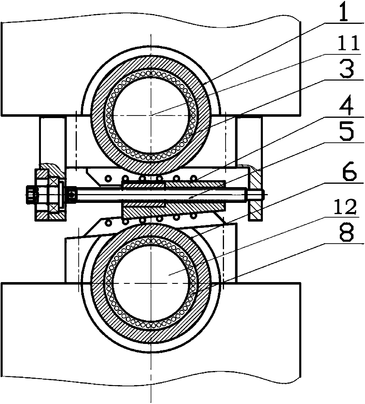
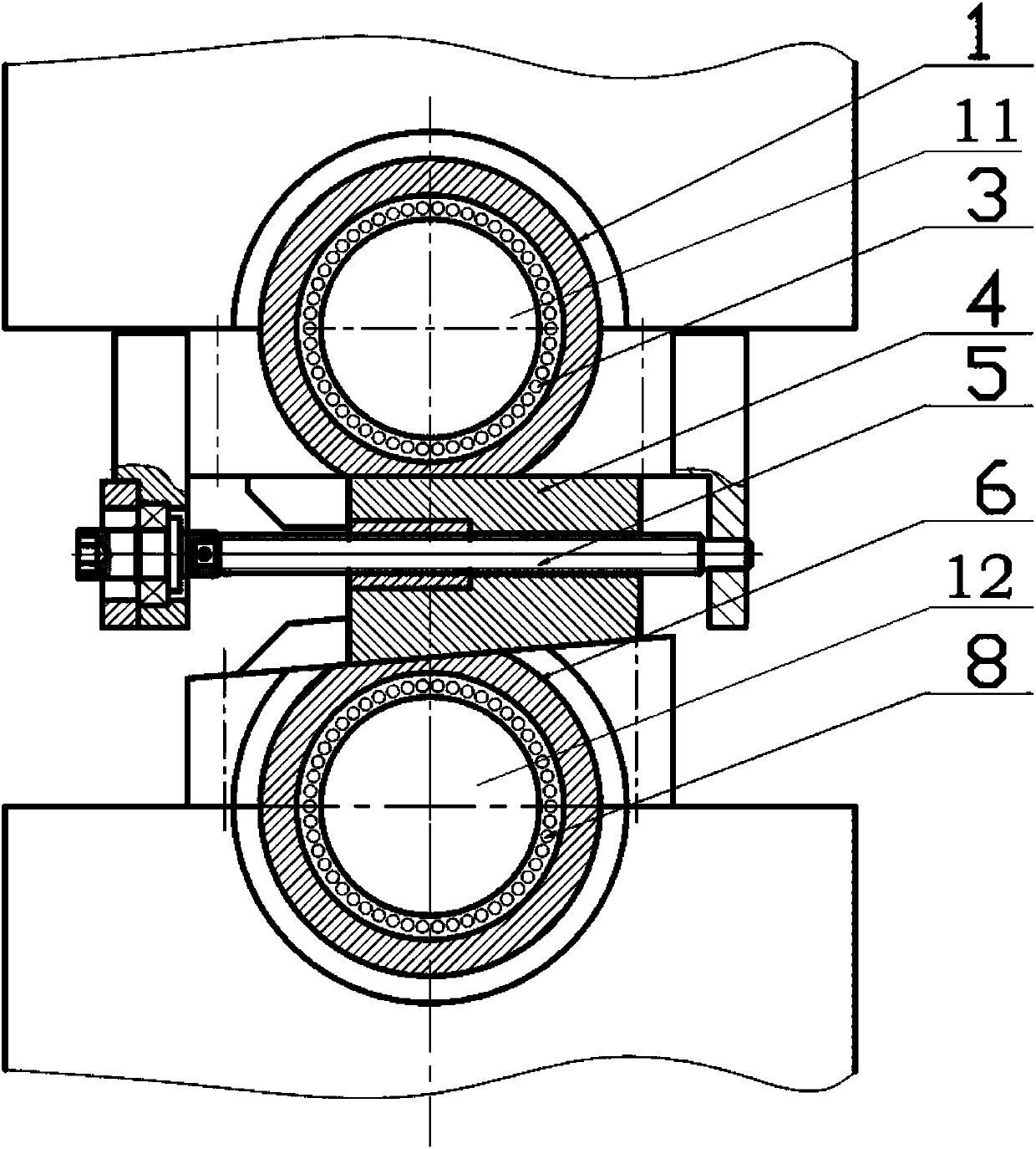
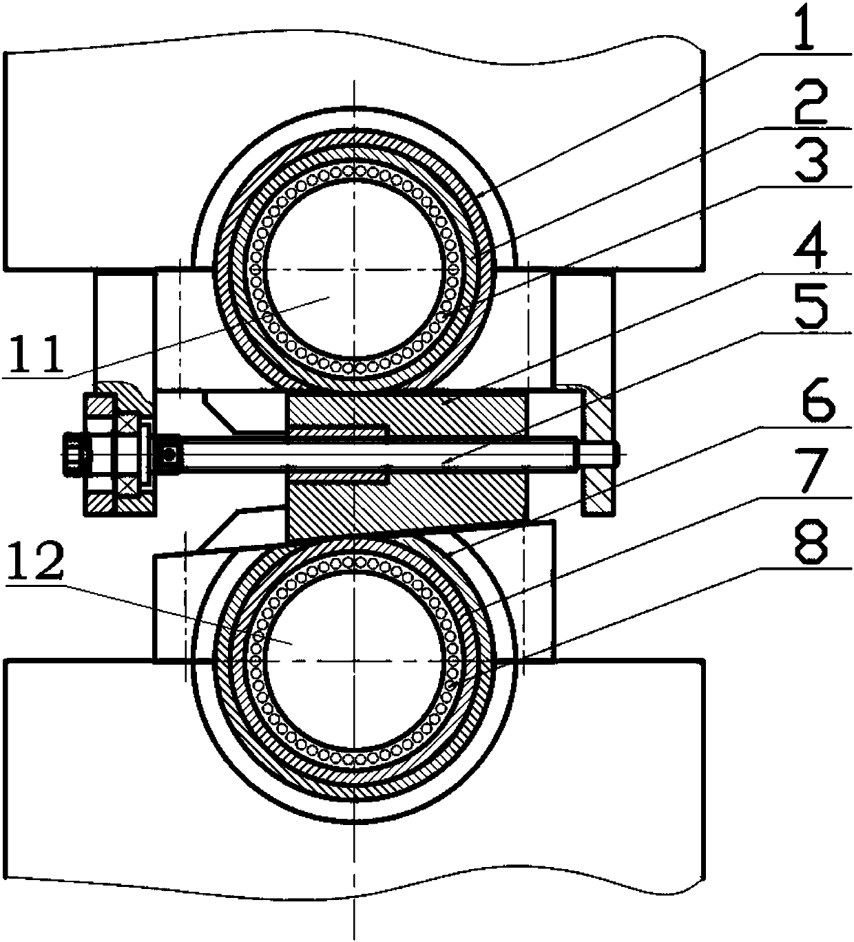
[0020] This application is aimed at the problems existing in the current adjustment of the axis spacing, for example: in the adjustment of the embossing shaft structure corresponding to printing by using the circular pressing circle structure, refer to figure 1 with ...


PUM


Abstract

The invention discloses a belling bearing spacing adjustment device. The belling bearing spacing adjustment device comprises two bearing packs arranged in the up-down direction and an adjustment device body arranged between the two bearing packs. A rotary shaft is arranged between the two sets of bearing packs, rolling bearings are arranged on the outer portion of the rotary shaft, at least two rolling bearings are arranged in the axial direction of the rotary shaft, a rotary movable sleeve is arranged at the outer ring of one rolling bearing, fixed bearing sleeves are arranged at the outer rings of the other rolling bearings, and the fixed bearing sleeves are fixedly connected with a bearing seat; the adjustment device comprises a rotary lead screw and an oblique iron block, the oblique iron block is provided with an inclined face, and the inclined face is in contact with the outer ring of the rotary moving sleeve in at least one bearing pack; and the oblique iron block can be drivento move in the axial direction through the rotary lead screw, and further the corresponding bearing packs can move up and down through the rotary moving sleeves being in contact with the inclined face. According to the belling bearing spacing adjustment device, spacing adjustment between two belling bearings can be rapidly and stably achieved, meanwhile the precision of spacing adjustment is improved, and the product yield is increased.

Description

technical field [0001] The invention relates to the technical field related to mechanical processing, in particular to a device for adjusting the distance between pressing and protruding shafts. Background technique [0002] In the field of mechanical processing, due to the connection and reciprocating characteristics of the circular structure, it is often suitable for the processing and preparation of various types of equipment or products. For example, in the field of packaging printing, the printing operation of the corresponding paper products is usually realized by using the in-line technology of circular embossing and embossing. Among them, the in-line circular embossing and embossing workstation is mainly composed of four parts: unwinding, printing, embossing, and rewinding. During the production process of round pressing and round pressing, the upper shaft of the pressing convex is generally a fixed shaft, the lower shaft is a movable shaft, and there is a hydraulic...

Claims


Application Information

Patent Timeline
Patent Type & Authority Applications(China)
IPC IPC(8): B41F13/26
CPCB41F13/26
Inventor 龙东平刘健书欧立国徐哲立代文继吴江
Owner CHANGDE JINPENG PRINTING
Why Eureka
Try Eureka