
Muzzle converting system of charging pile

A conversion system and charging pile technology, which is applied in the electric power field, can solve problems such as poor adaptability, and achieve the effect of improving adaptability and facilitating charging operations

Inactive Publication Date: 2018-02-23
STATE GRID SHANDONG ELECTRIC POWER CO TAOXIAN POWER SUPPLY CO
View PDF4 Cites 15 Cited by
  • Summary
  • Abstract
  • Description
  • Claims
  • Application Information

AI Technical Summary

Problems solved by technology

[0003] The charging pile system for electric vehicles is used as a terminal for car owners to purchase electricity to supplement power for electric vehicles. It can realize timing, electricity metering and amount charging, but it faces poor adaptability in practical applications, such as: currently At least five electric vehicle charging interfaces and standards are popular in the world. There are also electric vehicles with national standard interfaces and electric vehicles with non-national standard interfaces from various manufacturers in the domestic market. Due to the late introduction of national standards, non-national standard electric vehicles accounted for About 80% of the existing electric vehicles, while most of the charging piles in China are single-interface standard charging piles, the charging pile network construction based on this traditional charging pile obviously cannot meet the needs of the market

Method used


Image

  • Muzzle converting system of charging pile
  • Muzzle converting system of charging pile
  • Muzzle converting system of charging pile

Examples


Embodiment 1

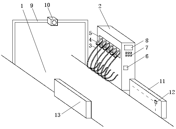
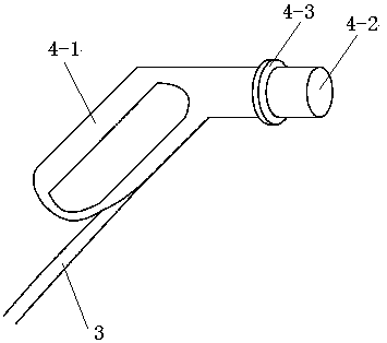
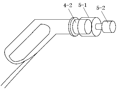
[0033] Such as Figure 1-4 As shown in , in this embodiment, a charging pile 2 is provided on one side of the vehicle passage 1, and the charging pile includes more than two charging guns 4 with different charging interface standards. Each charging gun and the corresponding charging circuit in the charging pile pass through The charging cable 3 is electrically connected; the charging pile is provided with a card position 5 corresponding to each charging gun for accommodating the charging gun, and the charging plug 4-2 of the charging gun is socketed in the card position for fixed charging The fixed sleeve 5-1 of the gun position, the rear end of the fixed sleeve is connected with an electric control pusher 5-2 to push the fixed sleeve forward or backward by the electric control pusher; a central control processing device is also provided, and the central control processing device It has a database that stores the electric vehicle model and the corresponding charging interface ...

Embodiment 2

[0039] Such as Figure 1-4 As shown in , in this embodiment, a charging pile 2 is provided on one side of the vehicle passage 1, and the charging pile includes more than two charging guns 4 with different charging interface standards. Each charging gun and the corresponding charging circuit in the charging pile pass through The charging cable 3 is electrically connected; the charging pile is provided with a card position 5 corresponding to each charging gun for accommodating the charging gun, and the charging plug 4-2 of the charging gun is socketed in the card position for fixed charging The fixed sleeve 5-1 of the gun position, the rear end of the fixed sleeve is connected with an electric control pusher 5-2 to push the fixed sleeve forward or backward by the electric control pusher; a central control processing device is also provided, and the central control processing device It has a database that stores the electric vehicle model and the corresponding charging interface ...

Embodiment 3

[0045] Such as Figure 1-4 As shown in , in this embodiment, a charging pile 2 is provided on one side of the vehicle passage 1, and the charging pile includes more than two charging guns 4 with different charging interface standards. Each charging gun and the corresponding charging circuit in the charging pile pass through The charging cable 3 is electrically connected; the charging pile is provided with a card position 5 corresponding to each charging gun for accommodating the charging gun, and the charging plug 4-2 of the charging gun is socketed in the card position for fixed charging The fixed sleeve 5-1 of the gun position, the rear end of the fixed sleeve is connected with an electric control pusher 5-2 to push the fixed sleeve forward or backward by the electric control pusher; a central control processing device is also provided, and the central control processing device It has a database that stores the electric vehicle model and the corresponding charging interface ...


PUM


Abstract

The invention relates to a muzzle converting system of a charging pile. The charging pile comprises two or more charging guns with different charging connector standards, wherein the charging guns areelectrically connected with a charging circuit separately; clamping positions corresponding to the charging guns in a one-to-one mode are arranged on the charging pile, fixing sleeves connected withcharging plugs of the charging guns in a sleeving mode are arranged in the clamping positions, and electrically-controlled pushers are connected to the rear ends of the fixing sleeves; the system is further provided with a central control and processing device, and the central control and processing device is provided with a database which stores type information of electric vehicles and corresponding charging connector information; the central control and processing device searches the database for the corresponding charging connector information and correspondingly controls one electrically-controlled pusher to push out the charging gun with a corresponding charging connector after receiving the type information of a vehicle which needs to be charged. By means of the system, the type information of the vehicle which enters a charging vehicle channel can be fast obtained, and the corresponding electrically-controlled pusher is controlled to push out the charging gun with the corresponding charging connector after the corresponding charging connector information is obtained through database searching, so that the adaptive capability of the charging pile is greatly improved.

Description

technical field [0001] The invention relates to the field of electric power technology, in particular to a charging pile muzzle conversion system. Background technique [0002] With the huge challenges facing the current energy and environmental issues, new energy electric vehicles are getting more and more attention. At present, the power supplement of new energy electric vehicles is mainly realized through charging piles, that is, the power batteries of electric vehicles are quickly and safely charged from charging piles. [0003] The charging pile system for electric vehicles is used as a terminal for car owners to purchase electricity to supplement power for electric vehicles. It can realize charging by timing, electricity meter and amount meter, but it faces the problem of poor adaptability in practical applications, such as: currently At least five electric vehicle charging interfaces and standards are popular in the world. There are also electric vehicles with nation...

Claims


Application Information

Patent Timeline
Patent Type & Authority Applications(China)
IPC IPC(8): B60L11/18
CPCB60L53/14B60L53/31B60L53/65Y04S30/12Y02T10/70Y02T90/167Y02T90/12Y02T10/7072Y02T90/14
Inventor 董哲鲁康涛董青叶王峰李慧琳王红霞吴娟明广存田栋张福才
Owner STATE GRID SHANDONG ELECTRIC POWER CO TAOXIAN POWER SUPPLY CO
Learn More