Lifting structure for transfer of large concrete blocks

A concrete and large-scale technology, which is applied in the field of hoisting structures for the transfer of large concrete blocks, can solve problems such as safety accidents, achieve the effect of ensuring personal safety and improving stability

Active Publication Date: 2019-03-22
CHINA MCC5 GROUP CORP
View PDF5 Cites 0 Cited by
  • Summary
  • Abstract
  • Description
  • Claims
  • Application Information

AI Technical Summary

Problems solved by technology

Aiming at the problem in the prior art that safety accidents are likely to occur during the removal process of the foundation pit support, especially the transfer of the inner support beam after cutting into sections, the applicant designed a method specially designed for the hoisting of relatively regular large concrete blocks process, to ensure that the small section of the inner support beam is always in a stable state during the hoisting process, completely eliminate the phenomenon that the small section of the inner support beam is separated from the steel bars bound to it in the prior art, and provide construction safety and reliability in the demolition process to ensure on-site personal safety of construction workers

Method used


Image

  • Lifting structure for transfer of large concrete blocks

Examples


Embodiment 1

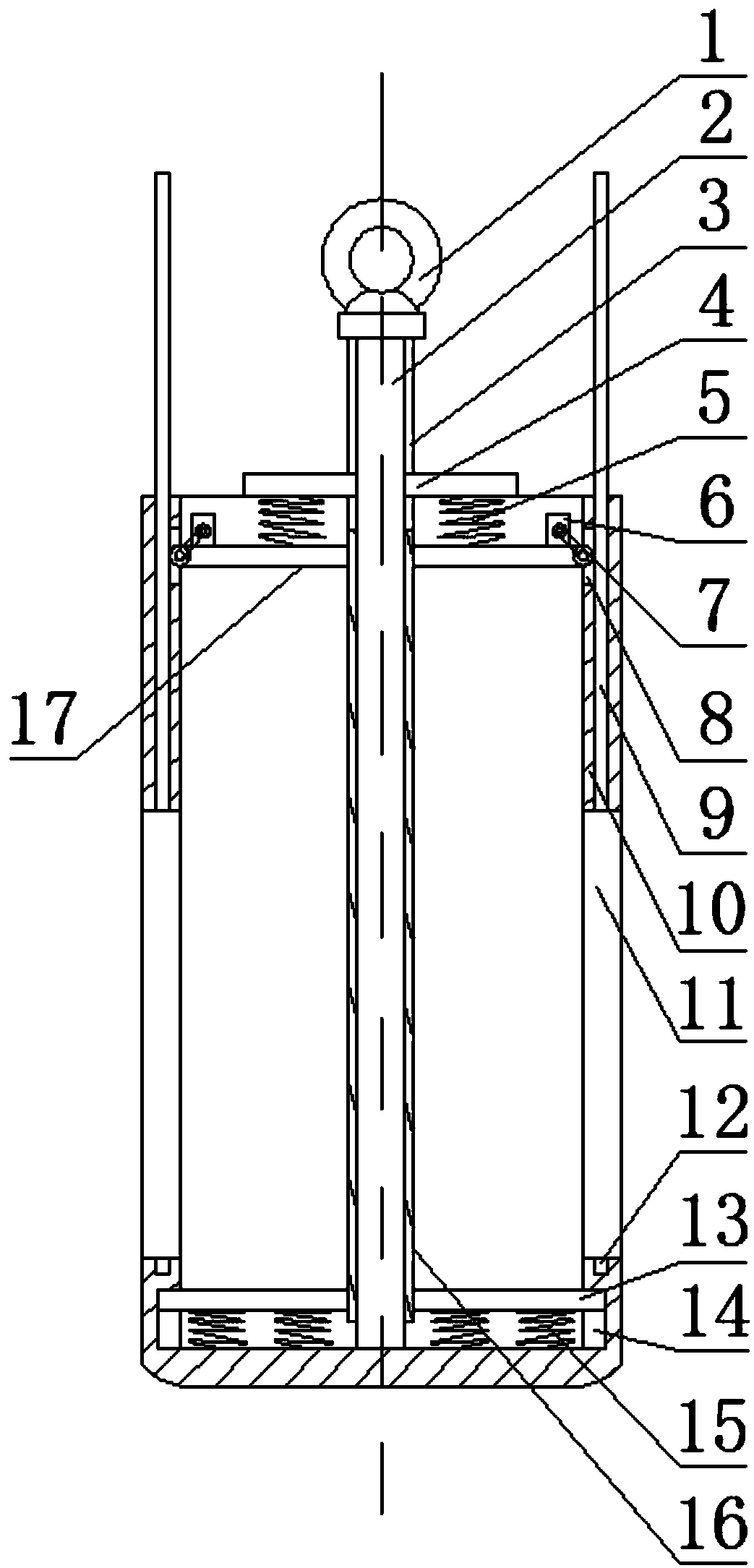
[0021] Such as figure 1 As shown, this embodiment includes a rectangular frame body 10 with an open upper end and a connecting rod 2, the upper end of the connecting rod 2 is fixed with a hanging ear 1, the lower end of the connecting rod 2 is placed in the frame body 10 and connected to the bottom of the frame body 10, and The two opposite side walls of the frame body 10 are respectively provided with feed inlets 11, and a sleeve 16 is sleeved on the outer peripheral wall of the connecting rod 2, and a sleeve 16 is provided on the upper end side wall along the axis of the sleeve 16. Two mutually symmetrical longitudinal grooves 3, the limit plate 4 is connected with the outer wall of the connecting rod 2 after passing through the longitudinal groove 3, and support plates 17 are respectively fixed on the two side walls of the sleeve 16, and the support plates 17 is connected with the limiting plate 4 through the first spring 5, the bottom plate 13 is respectively fixed on the ...

Embodiment 2

[0024] Such as figure 1 As shown, in this embodiment, a channel communicating with the feed inlet 11 is provided on two opposite side walls of the frame body 10 , and the side baffle 9 is slidably disposed in the channel. After putting the small section of the inner support beam into the frame body 10, and when other construction wastes continue to be put in, the upper end of the inner support beam is filled with relatively small residual blocks to make full use of the inside of the frame body 10. The space is finally moved down by the side baffle plate 9 in the channel to close the feed port 11, preventing the inner supporting beam segments or fragments from falling from the inside of the frame body 10.

[0025] A toothed belt is provided on the inner side wall of the side baffle 9, an opening 8 communicating with the channel is provided on the inner side wall of the upper section of the frame body 10, and a motor 6 is provided on the two support plates 17, and The outer end...


PUM


Abstract

The invention discloses a hoisting structure for large concrete block transfer. The hoisting structure comprises a frame body and a connecting rod. A hanging lug is fixedly arranged at the upper end of the connecting rod. Feeding openings are correspondingly formed in the two opposite side walls of the frame body. The peripheral wall of the connecting rod is sleeved with a sleeve. Support plates are correspondingly and fixedly arranged on the two side walls of the sleeve and are connected with a limiting plate through first springs. A bottom plate is fixedly arranged on the two side walls of the lower section of the sleeve. Sliding grooves are correspondingly formed in the two inner side walls of the lower section of the frame body. The end of the outer side of the bottom plate is arrangedin the sliding grooves. Multiple second springs are arranged at the bottom of the frame body and are connected with the lower surface of the bottom plate. By the adoption of the hoisting structure for large concrete block transfer, it can be guaranteed that the small section of an inner support beam is always in the stable state in the hoisting and transfer processes, the phenomenon that the small section of the inner support beam is disengaged from rebars bundled to the small section of the inner support beam in the prior art is completely eradicated, the construction safety and reliabilityin the dismantling process are provided, and the personal safety of constructors on the site is guaranteed.

Description

technical field [0001] The invention relates to the field of building construction, in particular to a hoisting structure for transferring large concrete blocks. Background technique [0002] The foundation pit support is to ensure the safety of the underground structure construction and the surrounding environment of the foundation pit, and the support, reinforcement and protection measures adopted for the side wall of the foundation pit and the surrounding environment. The support in the foundation pit is a kind of foundation pit support. After the construction of the underground structure in the foundation pit is completed, and the gap between the foundation pit and the outer wall of the underground structure is backfilled, the internal support needs to be removed. The internal support beam is one of the main components of the internal support structure. When removing the internal support beam, it is necessary to remove the small beam first, then the main beam; first rem...

Claims


Application Information

Patent Timeline
Patent Type & Authority Patents(China)
IPC IPC(8): B66C1/10
CPCB66C1/10
Inventor 杨忠富白松高长玲
Owner CHINA MCC5 GROUP CORP
Why Eureka
Try Eureka