Steel frame beam column rigid-connection joint node based on socket welding type connection

A technology for connecting joints and steel frames, applied in the engineering field, can solve problems such as difficulty in anchoring and connecting of steel bars, complex beam-column joint structure, and large on-site welding workload, and achieves light weight, reliable rigid connection relationship, and architectural layout impact. small effect

Inactive Publication Date: 2018-02-23
厦门合立道工程设计集团股份有限公司
View PDF5 Cites 2 Cited by
  • Summary
  • Abstract
  • Description
  • Claims
  • Application Information

AI Technical Summary

Problems solved by technology

This method has many problems such as complex structure of beam-column joints, difficulty in anchoring and connection of steel bars, etc., and the construction is difficult; the method of auxiliary connection of section steel also has the disadvantage of large welding workload on site

Method used


Image

  • Steel frame beam column rigid-connection joint node based on socket welding type connection
  • Steel frame beam column rigid-connection joint node based on socket welding type connection
  • Steel frame beam column rigid-connection joint node based on socket welding type connection

Examples


Embodiment 1

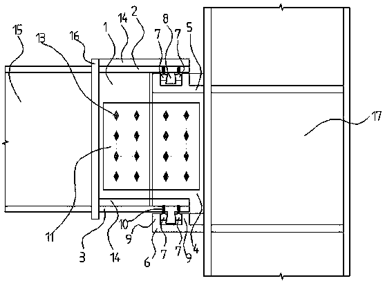
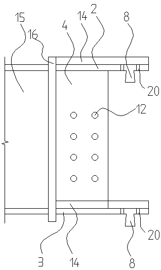
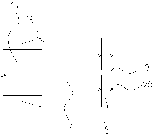
[0032] Such as Figure 1 to Figure 4 As shown, this embodiment 1 discloses a steel frame beam-column rigid connection based on a socket connection, including a connection end and a support end, and the connection end includes a web connection piece 1 at the connection end, an upper flange connection piece at the connection end 2 and the lower flange connector 3 at the connecting end, the upper flange connector 2 at the connecting end and the lower flange connector 3 at the connecting end are respectively located on the upper and lower sides of the web connector 1 at the connecting end, and the upper flange connector 2 at the connecting end The same length as the lower flange connector 3 at the connecting end, and the right side protrudes from the web connecting member 1 at the connecting end; the support end includes the web connecting member 4 at the support end, the upper flange connector 5 at the support end and The lower flange connector 6 at the support end, the upper fla...

Embodiment 2

[0055] Such as Figure 7~9 As shown, the structural difference between a steel frame beam-to-column rigid connection node based on socket connection of embodiment 2 and embodiment 1 is:

[0056] The lengths of the upper flange connector 2 of the connection end and the lower flange connector 3 of the connection end are different, the right side of the upper flange connector 2 of the connection end protrudes from the web connector 1 of the connection end, and the lower flange connector 3 of the connection end It is flush with the web connecting piece 1 at the connecting end; the upper flange connecting piece 5 at the support end and the lower flange connecting piece 6 at the supporting end have the same length, and the left side of the upper flange connecting piece 5 at the supporting end is in line with the web of the supporting end The plate connecting piece 4 is flush, and the left side of the lower flange connecting piece 6 at the support end protrudes from the web connectin...


PUM


Abstract

The invention relates to the technical field of engineering, and discloses a steel frame beam column rigid-connection joint node based on socket welding type connection. The joint node comprises a connecting end, a support end and a socket welding pin, connection end shear-pins are arranged on the right side of a connection end upper flange connector and the right side of a connection end lower flange connector respectively, multiple support end shear-pins are arranged on the left side of a support end upper flange connector and the left side of a support end upper flange connector respectively, two parallel support end shear-pins form a shear groove, the connection end shear-pins are inserted into the shear groove, and the socket welding pins are inserted into gaps between the connectionend shear-pins and the shear groove and installed and fixed with set screws. Accordingly, by means of socket welding type connection, the pulling and pressing force of a beam upper flange plate and abeam lower flange plate is effectively transmitted through physical geometry contact of the socket welding pins, and the machining precision requirements of a component are low; compared with the prior art, installation is convenient, reliability is high, and meanwhile the node and the component achieve detachable reutilization.

Description

technical field [0001] The invention relates to the technical field of engineering, in particular to a steel frame beam-column rigid connection node based on a socket connection. Background technique [0002] In recent years, with the development of housing industrialization, prefabricated buildings will usher in a new blowout development. Prefabricated buildings mainly include prefabricated concrete structures (PC) and prefabricated steel structures. Among them, due to its material and processing characteristics, the steel structure has achieved factory production of a large number of components at this stage, and its promotion as a prefabricated building has strong vitality. In 2016, my country's crude steel output was 808 million tons, accounting for 50% of the world's steel output. The steel specifications and product quality were close to or reached the international advanced level, but the overcapacity situation was serious. During the same period, my country's steel ...

Claims


Application Information

Patent Timeline
Patent Type & Authority Applications(China)
IPC IPC(8): E04B1/24E04B1/58
CPCE04B1/2403E04B2001/2406E04B2001/2412E04B2001/2418
Inventor 陈德平陈跃辉
Owner 厦门合立道工程设计集团股份有限公司
Why Eureka
Try Eureka