

Multi-directional adjusting down lamp
A multi-directional adjustment, downlight technology, applied in the field of LED lighting, can solve the problems of rising maintenance costs, difficulty in debugging, and increased humanized demand for lamps, and achieve the effects of improving adaptability, firm structure, and stable expansion and contraction.
- Summary
- Abstract
- Description
- Claims
- Application Information
AI Technical Summary
Problems solved by technology
Method used
Image

Examples
Embodiment 1
[0025] The invention provides a downlight that can realize multi-direction adjustment such as vertical expansion and contraction, horizontal rotation, and irradiation angle deflection.
[0026] The downlight specifically includes adjustment mechanisms in three directions, and also includes a control module for controlling these adjustment mechanisms.
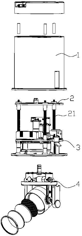
[0027] In terms of overall structure, such as figure 1 As shown, it includes a housing, an adjustment bracket arranged in the housing and parallel to the axial direction of the lamp body, an adjustment platform installed on the adjustment bracket, and a light source unit installed on the adjustment platform. The adjustment bracket is used for fixing the light source part and cooperating with a plurality of adjustment mechanisms. The adjustment bracket includes a plurality of transmission tooth rods coaxial with the lamp body. In order to ensure that the light source can expand and contract smoothly, the number of transmission t...
Embodiment 2
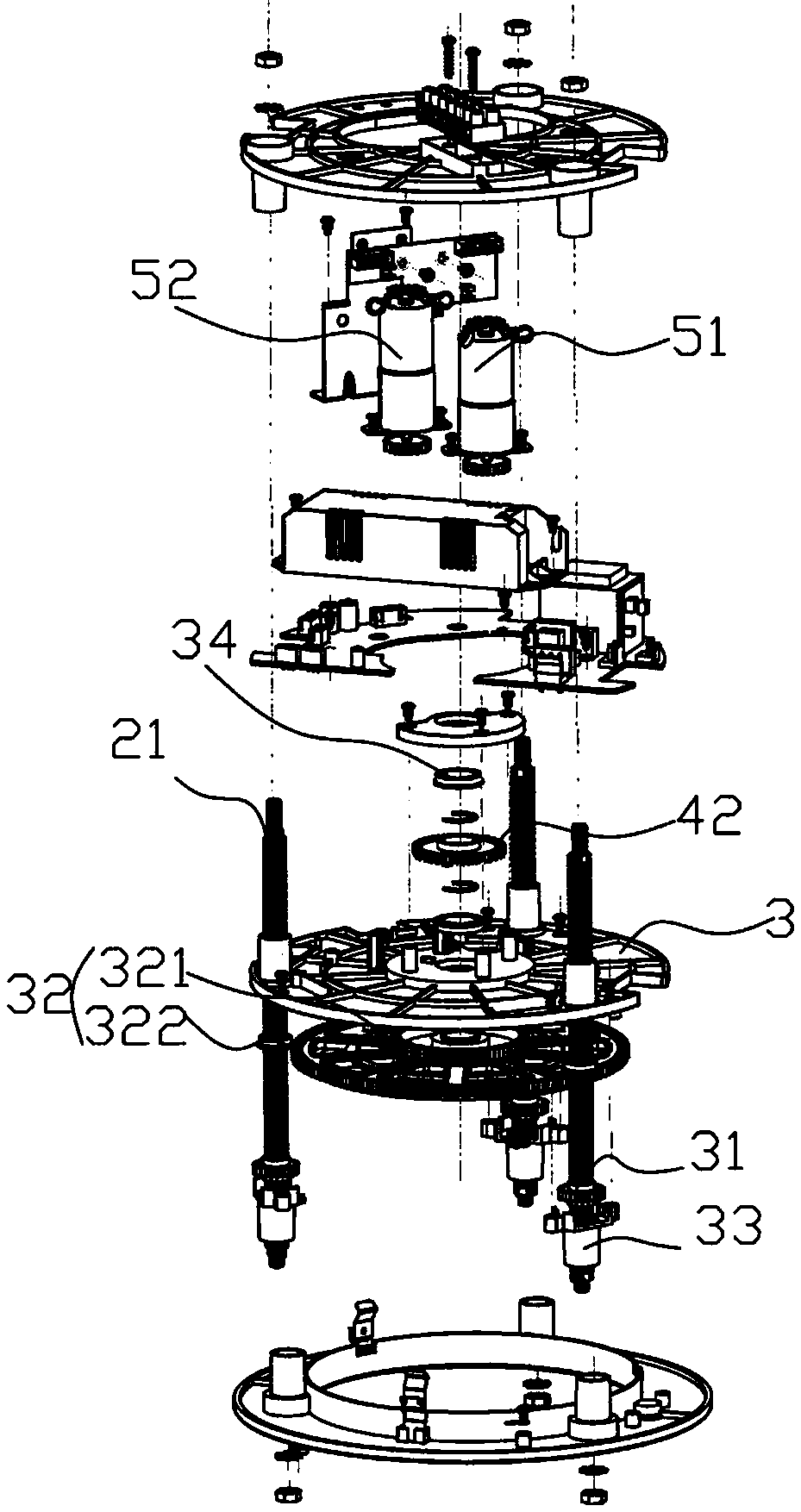
[0031] As a supplement to Embodiment 1, the difference between this embodiment and Embodiment 1 is that, as figure 2 As shown, the shape of the adjustment platform in this embodiment matches the shape of the downlight, and is approximately circular. A plurality of transmission tooth bars pass through the edge of the adjustment platform, and the lower surface of the adjustment platform is provided with transmission gears and toothed discs. , The transmission structure is formed by the transmission gear between the chainring and the transmission tooth rod. Wherein the transmission gear is sleeved on the transmission tooth rod, and its inner wall is provided with internal teeth matching with the thread of the transmission tooth rod, and the outer wall is provided with external teeth matching with the tooth disc. When the chainring rotates, it drives the transmission gear to rotate. During the rotation of the transmission gear, its internal teeth will cause the horizontal positio...
Embodiment 3
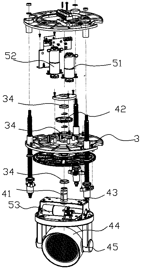
[0036] As a supplement to Embodiments 1 and 2, the difference between this embodiment and Embodiment 1 is that, as image 3 As shown, on the horizontal rotating structure, the top of the light source part is connected with a horizontal rotating structure that passes through the adjustment platform. It is fixedly connected with the gear plate and the adjustment platform to ensure its free rotation without affecting the rotation of the gear plate. The end of the horizontal rotation structure is fixed with a horizontal rotation gear, and the second drive motor fixed above the adjustment platform engages with the horizontal rotation gear and drives it to rotate.
PUM
 Abstract
Description
Claims
Application Information