Magnetic refrigerator

A magnetic refrigerator, piston mechanism technology, applied in refrigerators, refrigeration and liquefaction, machines using electro/magnetic effects, etc., can solve the problems of complicated pipeline circulation, achieve the effect of simplifying the system structure and avoiding the fluid distribution method

Pending Publication Date: 2018-02-23
GREE ELECTRIC APPLIANCES INC
View PDF0 Cites 17 Cited by
  • Summary
  • Abstract
  • Description
  • Claims
  • Application Information

AI Technical Summary

Problems solved by technology

When the magnetic field magnetizes the magnetocaloric material, the magnetocaloric material becomes hot; when the magnetic field is removed, the magnetocaloric material becomes cold, and magnetic refrigeration uses the phenom

Method used


Image

  • Magnetic refrigerator
  • Magnetic refrigerator
  • Magnetic refrigerator

Examples


Embodiment 1

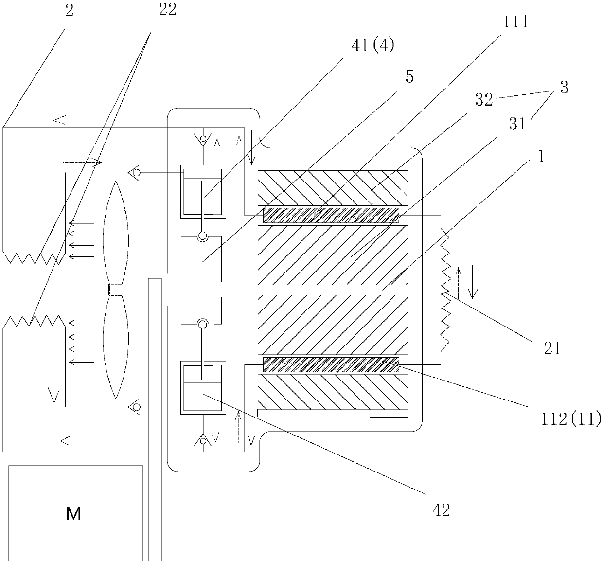
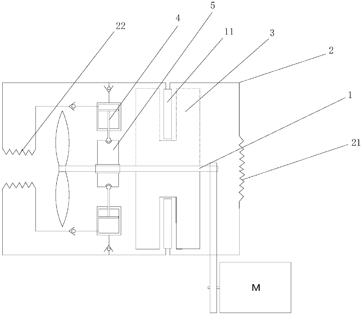
[0069] The number of the magnetic field generator 3 and the magnetocaloric material bed 11 is two, and the magnetic field generator 3 and the magnetocaloric material bed 11 are semicircular structures, and the magnetic field generator 3 includes a rotor 31 and a stator 32, and the rotors 31 of the two magnetic field generators 3 form a circular structure and are sleeved on the rotating shaft 1, and rotate with the rotating shaft 1, and the two stators 32 are arranged on the outside of the circular structure, and An annular magnetic exchange area is formed with the circular structure, and the two magnetocaloric material beds 11 are located in the annular magnetic exchange area.

[0070] The driving device is a cam and a piston mechanism 4. The cam is fixedly arranged on the rotating shaft 1 and rotates freely with the rotating shaft 1. At the same time, the outer surface of the cam cooperates with the two piston mechanisms 4 to drive the two piston mechanisms 4 to movement in o...

Embodiment 2

[0077] The difference from Example 1 is that the magnetic field generator has a C-shaped cross section, and the C-shaped opening faces away from the rotation axis, and the two magnetocaloric material beds 11 are located in the ring-shaped magnetic exchange area formed after the C-shaped opening rotates. middle.

Embodiment 3

[0079] Different from Embodiment 2, the number of the magnetic field generators 3 is multiple, and a plurality of ring-shaped magnetic exchange areas are formed on the peripheral side of the rotating shaft, and the number of the magnetocaloric material beds 11 is also multiple, and Distributed in different annular magnetic exchange areas as required.


PUM


Abstract

The invention provides a magnetic refrigerator. The magnetic refrigerator comprises a rotating shaft, a plurality of heat exchanging pipelines which are arranged at the circumferential side of the rotating shaft, and at least two magnetic field generators, wherein all magnetic field generators are uniformly distributed on the rotating shaft. According to the magnetic refrigerator, the heat exchanging pipelines are independent from each other, so that each heat exchanging pipeline can be kept in an independent working state and does to interfere others, and fluid exchanging can also be avoided;in addition, two magnetic heating material beds are provided, so that fluid can pass through the magnetic material beds to be subjected to demagnetizing and cooling while flowing to a cold end, thusthe fluid with different temperature in the same heat exchanging pipeline can be prevented from mixing which leads to the decrease of refrigerating capacity, and the cold produced through a magnetic medium is fully utilized; a driving device is arranged and capable of supplying flowing power to the fluid in each heat exchanging pipeline, and moreover, the flowing direction of the fluid can be controlled; a complex fluid distributing method is avoided, and the system structure is simplified.

Description

technical field [0001] The invention relates to the technical field of magnetic refrigeration, in particular to a magnetic refrigerator. Background technique [0002] Magnetic refrigeration technology is a new type of refrigeration technology based on the magnetocaloric effect, which refers to the physical phenomenon that magnetocaloric materials release or absorb heat when the magnetic field increases or decreases. When the magnetic field magnetizes the magnetocaloric material, the magnetocaloric material becomes hot; when the magnetic field is removed, the magnetocaloric material becomes cold, and magnetic refrigeration uses the phenomenon of magnetocaloric effect to achieve the purpose of refrigeration, but the existing rotary magnetic refrigerator has The pipeline cycle is complicated, and problems such as fluid reversing distribution valves are required. Contents of the invention [0003] In order to solve the above technical problems, a magnetic refrigerator with a ...

Claims


Application Information

Patent Timeline
IPC IPC(8): F25B21/00
CPCF25B21/00F25B2321/0022Y02B30/00
Inventor 汪魁路文博罗胜杨蓉
Owner GREE ELECTRIC APPLIANCES INC
Why Eureka
Try Eureka