An optical cable high-altitude fusion splicing device

A fusion splicing and optical cable technology, applied in the field of optical cable high-altitude fusion splicing devices, can solve the problems of inconvenient portability, failure to timely failure, and long construction time, and achieve the effects of improving flexibility, reducing impact, and facilitating adjustment

Active Publication Date: 2020-04-21
ANHUI COMM IND SERVICE CO LTD
View PDF4 Cites 0 Cited by
  • Summary
  • Abstract
  • Description
  • Claims
  • Application Information

AI Technical Summary

Problems solved by technology

[0003] At present, in the prior art, there is also a method of using scaffolding to complete the fault handling of optical cables. The scaffolding requires a lot of materials and takes a long time to build.
And every time a fault is dealt with, scaffolding needs to be rebuilt, and the height of different towers must be met, which takes a lot of time and a long maintenance cycle, so that not only the fault cannot be processed in time, but also it is not easy to carry

Method used


Image

  • An optical cable high-altitude fusion splicing device
  • An optical cable high-altitude fusion splicing device
  • An optical cable high-altitude fusion splicing device

Examples


Embodiment

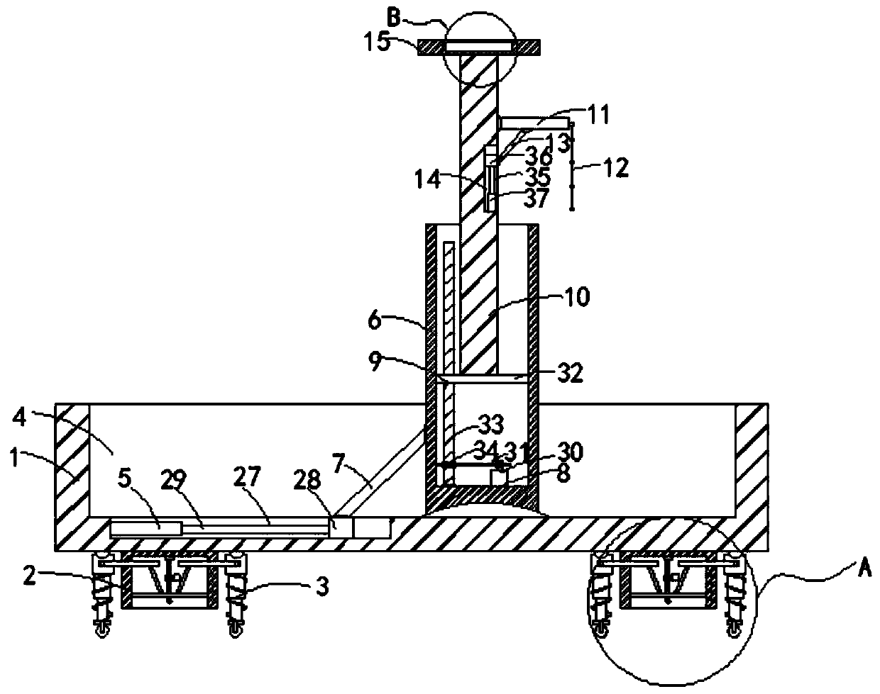
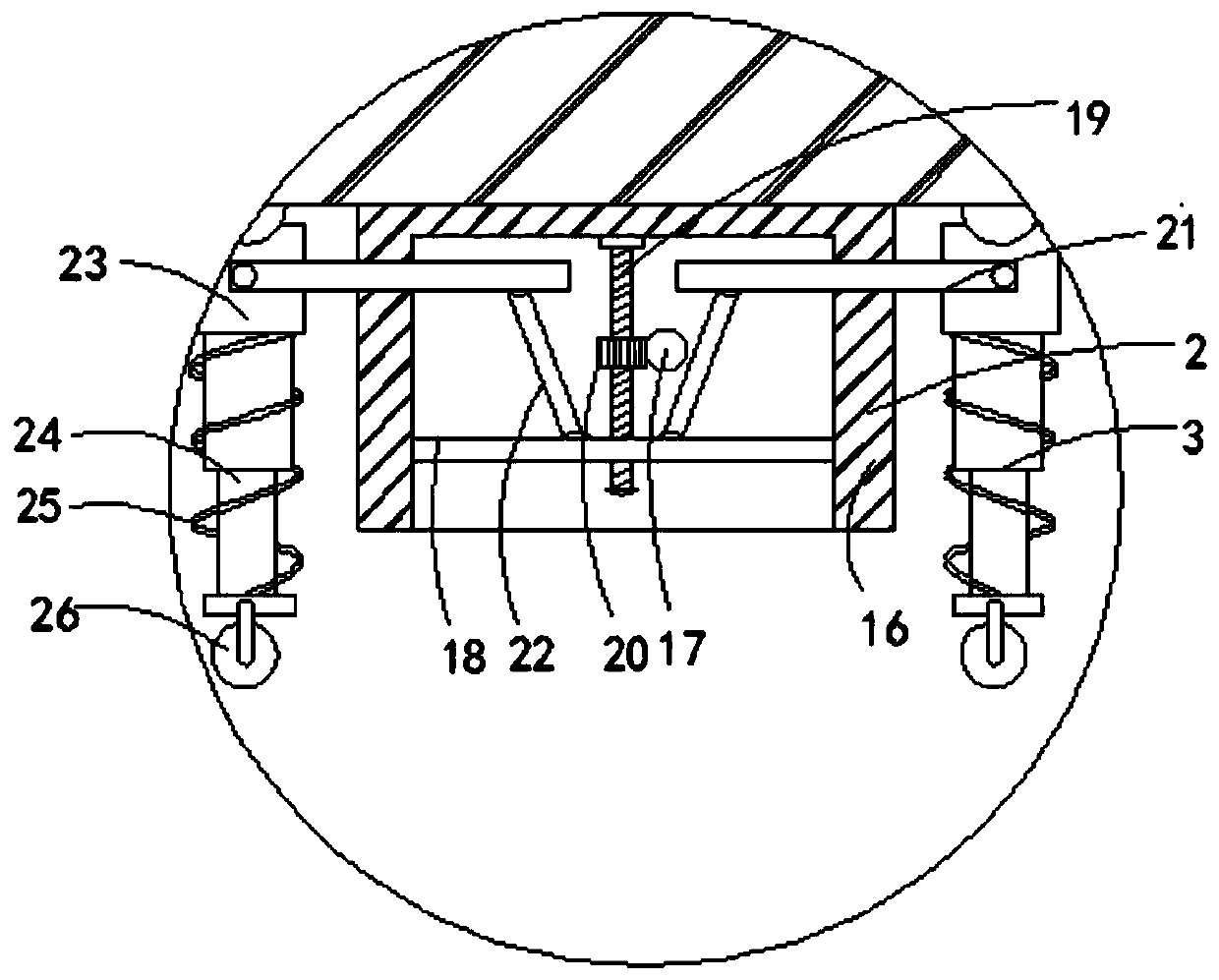
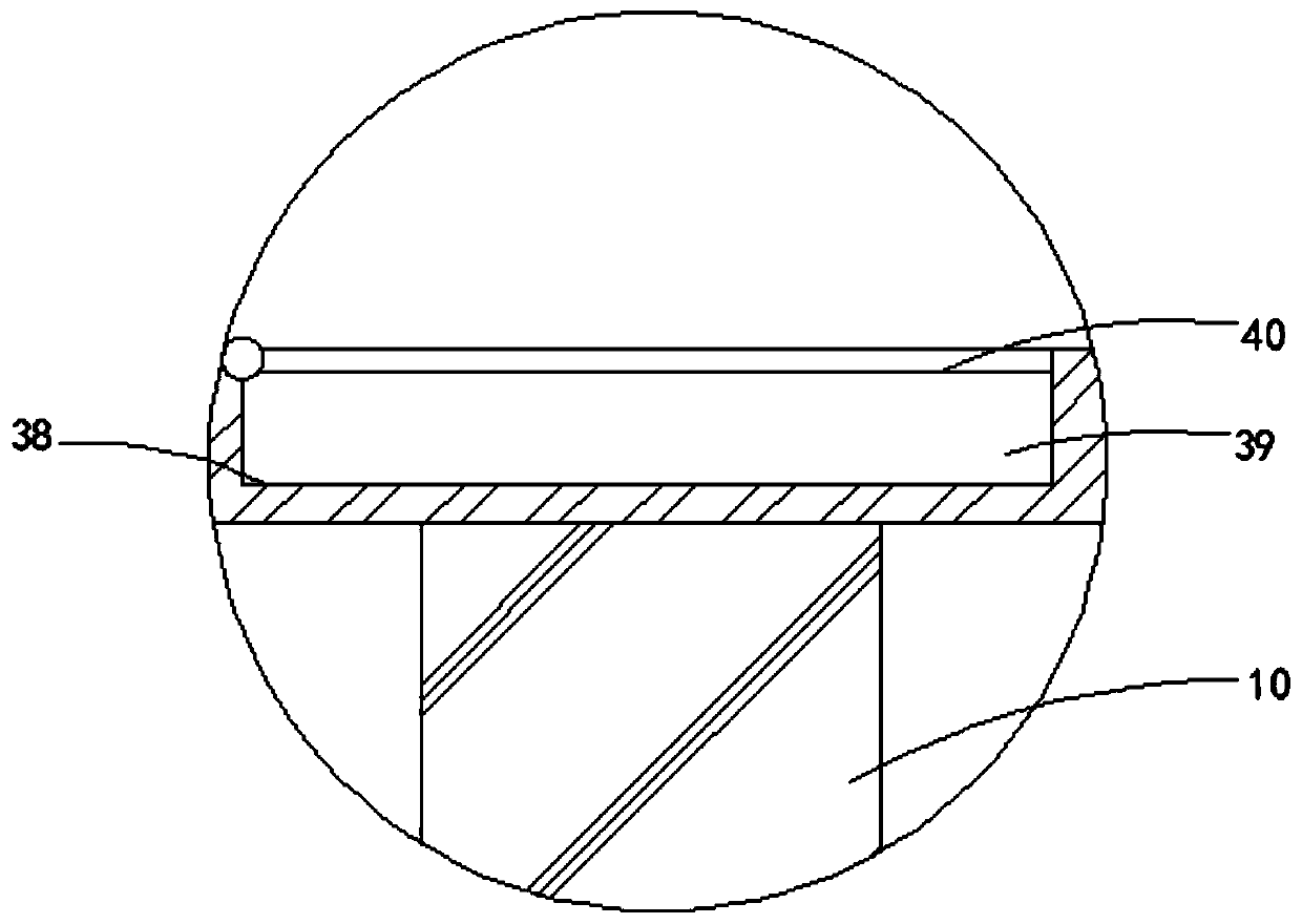
[0022] Such as Figure 1-4 As shown, a high-altitude fusion splicing device for optical cables includes a base 1. A plurality of control devices 2 are provided at the lower end of the base 1. The lower ends of the base 1 on the left and right sides of the control device 2 are rotatably connected with a moving mechanism 3. The upper end of the base 1 is provided with Groove 4, the bottom of the groove 4 is provided with a first sliding mechanism 5, the bottom of the groove 4 is rotatably connected with a first cylindrical barrel 6, and the opening of the first cylindrical barrel 6 is set upward, and the first cylindrical barrel 6 is close to the first One end side wall of the sliding mechanism 5 is rotationally connected with one end of the first linkage rod 7, and the other end of the first linkage rod 7 is rotationally connected with the first sliding mechanism 5. The bottom of the first cylindrical barrel 6 is provided with a rotating device 8, The first cylinder barrel 6 is...


PUM


Abstract

The invention belongs to the technical field of optical cable welding devices and particularly relates to a high-altitude welding device of an optical cable. The device comprises a base. The lower endof the base is provided with multiple control devices. Left and right sides of the control devices are rotatingly connected to moving mechanisms at a lower end of the base, and an upper end of the base is provided with a groove. The bottom of the groove is provided with a first sliding mechanism and is rotatingly connected to a first cylindrical barrel. An opening of the cylindrical barrel is upwardly arranged, and a side wall of the first cylindrical barrel close to the first sliding mechanism is rotatingly connected to one end of a first linkage rod. The other end of the first linkage rod is rotatingly connected to the first sliding mechanism. The bottom of the first cylindrical barrel is provided with a rotating device. The first cylindrical barrel is internally provided with a liftingmechanism which is in driving connection with the rotating device. An upper end of the lifting mechanism is provided with a support rod, and a side wall of the support rod is rotatingly connected toa support plate. The high-altitude welding device has the advantages that a fault can be handled in time and the welding device is easy to carry.

Description

technical field [0001] The invention belongs to the technical field of optical cable welding devices, and in particular relates to an optical cable high-altitude welding device. Background technique [0002] Optical cable is the main transmission tool of various information networks. Due to the limitation of the length of optical cable production, in order to ensure long-distance transmission, an optical cable connection box will be installed at a certain distance during the overhead laying process of the optical cable and the power high-voltage line on the same pole. At the same time, for the convenience of daily operation and maintenance, part of the optical cable, that is, the remaining cable, will be reserved at the position of the tower where the splicing box of the overhead optical cable is located. The fiber in the box is re-spliced. [0003] At present, in the prior art, there is also a method of using scaffolding to complete the fault handling of the optical cable....

Claims


Application Information

Patent Timeline
Patent Type & Authority Patents(China)
IPC IPC(8): G02B6/255
CPCG02B6/2553
Inventor 项晓元刘成莹杨振亚
Owner ANHUI COMM IND SERVICE CO LTD
Why Eureka
Try Eureka