Display panel, manufacturing method thereof and display device

A display panel and display layer technology, which is applied in the direction of semiconductor devices, electrical components, circuits, etc., can solve the problems of affecting the display effect of the display panel, color crosstalk, and difficult to achieve high-resolution display panel preparation, etc., to achieve high-resolution production rate effect

Active Publication Date: 2018-02-23
SHANGHAI TIANMA MICRO ELECTRONICS CO LTD
View PDF3 Cites 31 Cited by
  • Summary
  • Abstract
  • Description
  • Claims
  • Application Information

AI Technical Summary

Problems solved by technology

[0003] In the technology of OLED display panel, since the light-emitting layer is made by printing process, it is difficult to realize the preparation of high-resolution display panel by adopting the traditional RGB pixel structure, which is affected by the precision of the equipment and the droplet size of the material of the light-emitting layer.
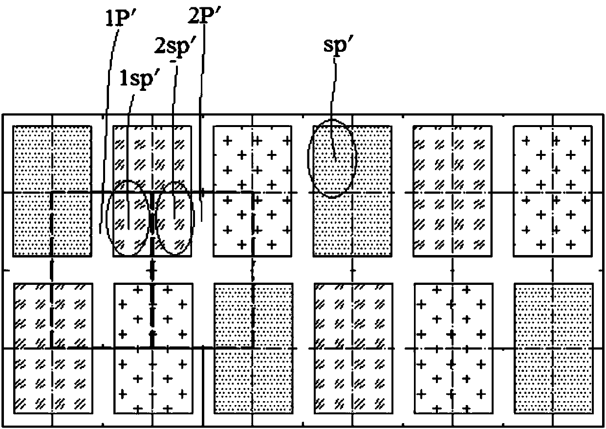
In the prior art, the sub-pixels of the same color in adjacent pixels share the openings on the mask, and the resolution is improved through different pixel designs. figure 1 It is a schematic top view of a display panel in the prior art, such as figure 1 As shown, in this technology, since the light-emitting devices of some sub-pixels sp' of two adjacent pixels 1P' and 2P' are connected together, when two pixels 1P' and 2P' are given different voltages, adjacent The mutual influence between the sub-pixels 1sp' and 2sp' of the same color in the pixel produces color crosstalk and affects the display effect of the display panel

Method used


Image

  • Display panel, manufacturing method thereof and display device
  • Display panel, manufacturing method thereof and display device
  • Display panel, manufacturing method thereof and display device

Examples


Embodiment Construction

[0033] Various exemplary embodiments of the present invention will now be described in detail with reference to the accompanying drawings. It should be noted that the relative arrangements of components and steps, numerical expressions and numerical values ​​set forth in these embodiments do not limit the scope of the present invention unless specifically stated otherwise.

[0034] The following description of at least one exemplary embodiment is merely illustrative in nature and in no way taken as limiting the invention, its application or uses.

[0035] Techniques, methods and devices known to those of ordinary skill in the relevant art may not be discussed in detail, but where appropriate, such techniques, methods and devices should be considered part of the description.

[0036] In all examples shown and discussed herein, any specific values ​​should be construed as exemplary only, and not as limitations. Therefore, other instances of the exemplary embodiment may have dif...


PUM


Abstract

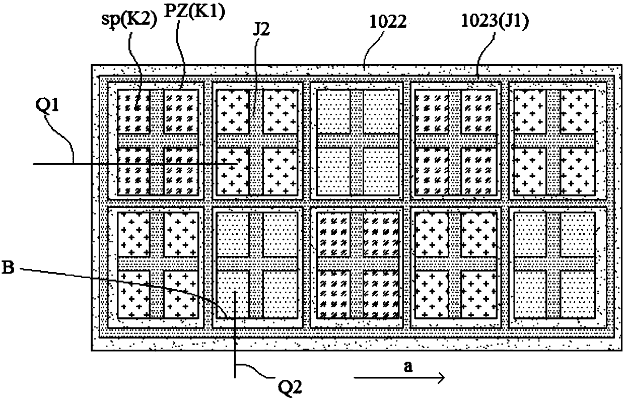
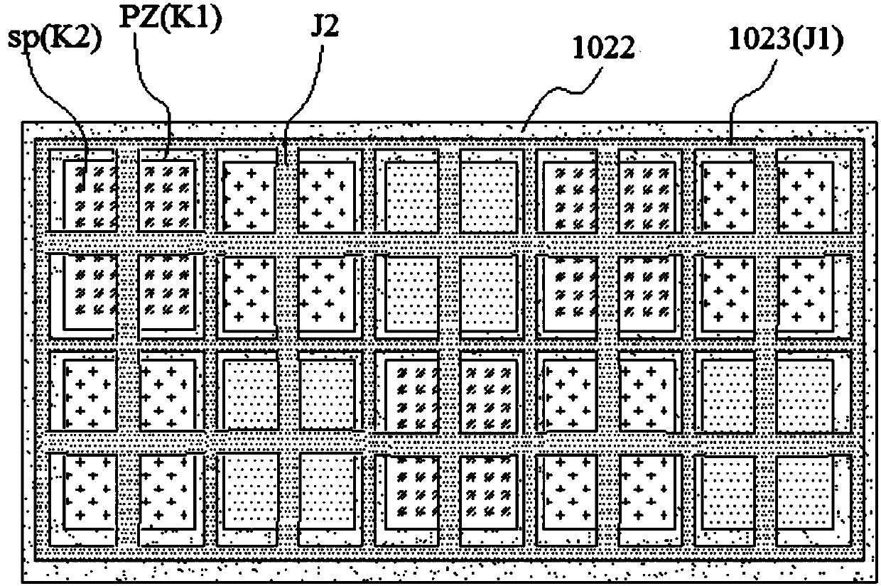
The invention discloses a display panel, a manufacturing method thereof and a display device. The display panel is provided with a plurality of pixel regions, and each pixel region consists of a plurality of subpixels of the same color. The display panel comprises an array substrate and a display layer, wherein the array substrate comprises a base layer and an array layer; the display layer is arranged on the side, away from the base layer, of the array layer; and the display layer comprises an anode metal layer, a first pixel defining layer, a second pixel defining layer and organic light-emitting layers; the anode metal layer is provided with a plurality of anodes, and one subpixel comprises one anode; the first pixel defining layer is arranged on the side, away from the array layer, ofthe anode metal layer, the first pixel defining layer is provided with a plurality of first openings exposing the anodes, and one pixel region comprises one first opening; the second pixel defining layer is prepared from a lyophobic material and comprises first defining parts on the first pixel defining layer and second defining parts positioned inside the first openings, the second defining partsare used for partitioning the first openings into a plurality of second openings, and one subpixel comprises one second opening; and the organic light-emitting layers are arranged inside each secondopening. The problem of color crosstalk for the display panel is solved.

Description

technical field [0001] The present invention relates to the technical field of semiconductors, and more particularly, to a display panel, a manufacturing method thereof, and a display device. Background technique [0002] Organic light-emitting diode (Organic Light-Emitting Diode, OLED) is also called organic electro-laser display, organic light-emitting semiconductor. OLED display technology has the advantages of self-illumination, wide viewing angle, almost infinitely high contrast ratio, low power consumption, and extremely high response speed. It is widely used in mobile phones, digital cameras, notebook computers, car audio, and televisions. [0003] In OLED display panel technology, since the light-emitting layer is produced by printing process, it is difficult to realize the preparation of high-resolution display panel by adopting the traditional RGB arrangement of pixel structure due to the influence of equipment precision and droplet size of the material of the ligh...

Claims


Application Information

Patent Timeline
Patent Type & Authority Applications(China)
IPC IPC(8): H01L27/32
CPCH10K59/122H10K59/1201
Inventor 霍思涛
Owner SHANGHAI TIANMA MICRO ELECTRONICS CO LTD
Why Eureka
Try Eureka