
Wire spring plug bush

A technology of wire springs and sockets, which is applied in the direction of electrical components, coupling devices, circuits, etc., can solve the problems of large space occupied by front-end sleeves, cumbersome process, and high manufacturing cost

Pending Publication Date: 2018-02-23
深圳市华南汇机科技有限公司
View PDF1 Cites 3 Cited by
  • Summary
  • Abstract
  • Description
  • Claims
  • Application Information

AI Technical Summary

Problems solved by technology

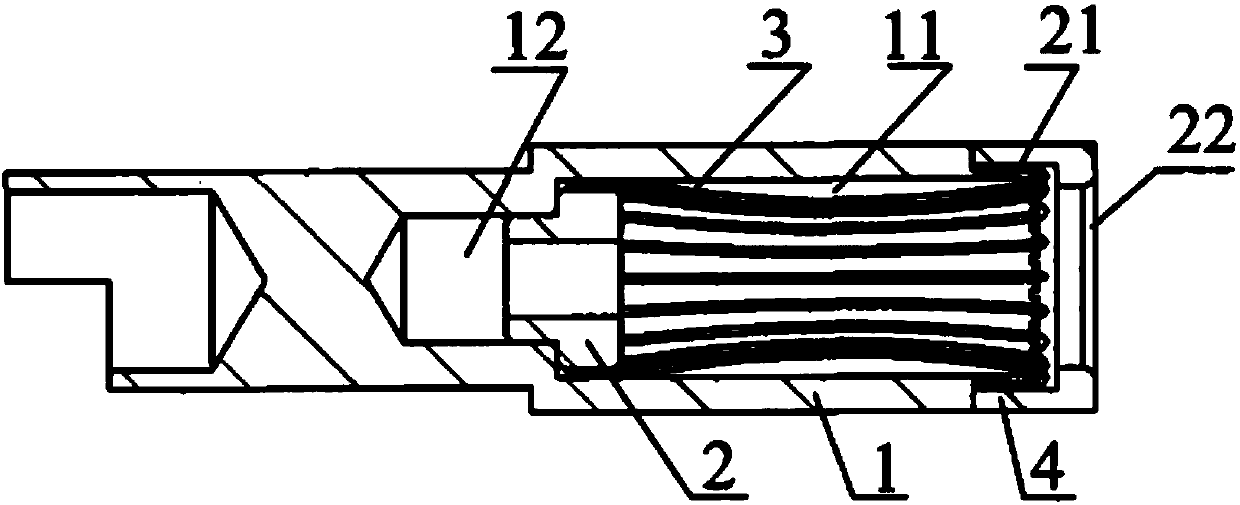
[0004] However, the wire spring socket disclosed in this patent has the following defects: on the one hand, the front end cap takes up a lot of space, making the overall structure not compact; High, cumbersome process

Method used


Image

  • Wire spring plug bush
  • Wire spring plug bush
  • Wire spring plug bush

Examples


Embodiment 1

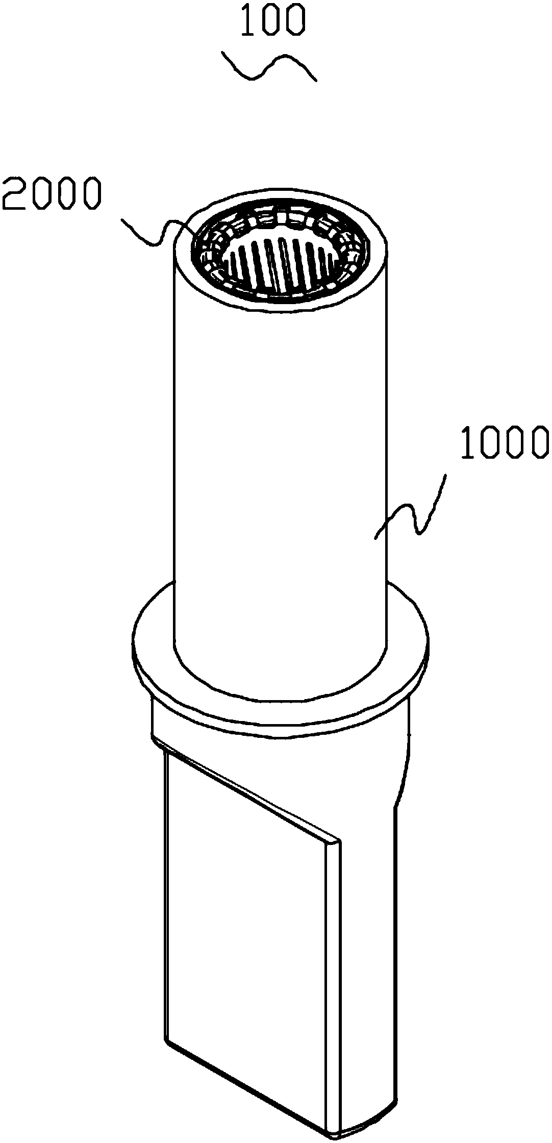
[0035] This implementation provides a wire spring socket 100, which is used in the technical field of conductive connectors. It cooperates with pins. When the pins are inserted into the wire spring socket 100, the conduction of circuits between different electrical components can be realized.

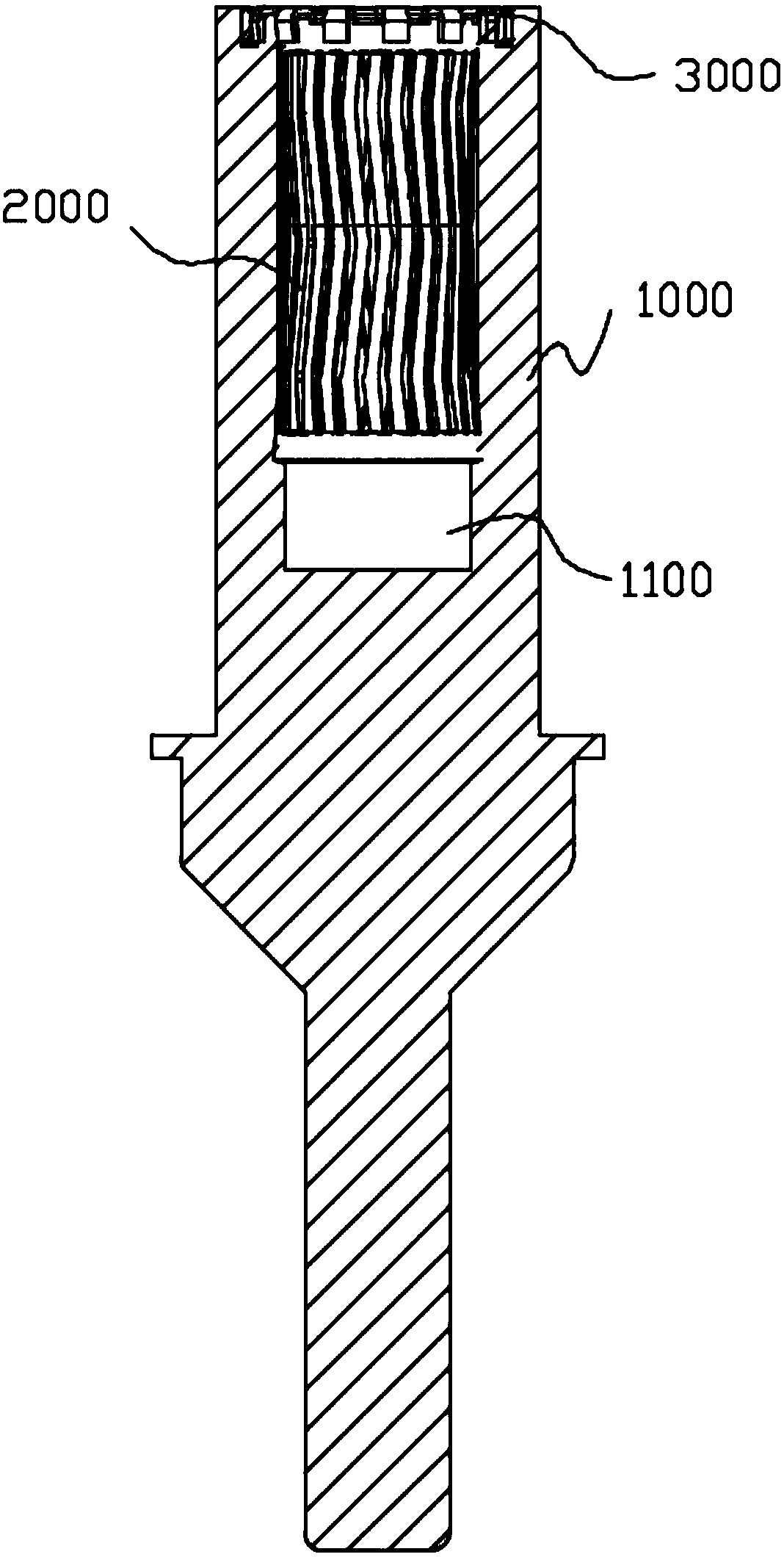
[0036] Specifically, see figure 2 , image 3 , Figure 4 with Figure 5 , The wire spring socket 100 includes an outer sleeve 1000 , a wire spring 2000 and a snap ring 3000 .

[0037] Wherein, the outer sleeve 1000 refers to the sleeve located on the outermost side of each sub-component of the wire spring sleeve 100 . It should be noted that, in this embodiment, a sleeve refers to any object with a hollow structure such as an internal through hole, a blind hole, etc., and its interior includes but is not limited to a circular, polygonal, tapered central hole or other forms. Hollow structure, its shape includes but not limited to cylinder, polyhedron and so on.

[0038] As a prefer...


PUM


Abstract

The invention provides a wire spring plug bush. The wire spring plug bush comprises an outer sleeve, a wire spring and a claming ring, wherein the outer sleeve has an inserting hole; the inserting hole adopts a blind hole structure and extends in the axial direction of the outer sleeve; a stage is arranged on the inner side of the inserting hole; an annular groove is formed in the end plane of theouter sleeve; the annular groove is close to the outer side edge of the inserting hole; multiple claws are arranged at the first end of the wire spring; the claws are mounted on the wall, positionedbetween the inserting hole and the annular groove, of the outer sleeve; the second end of the wire spring is mounted on the stage; and the clamping ring is clamped in the annular groove and used for fixing the claws. According to the wire spring plug bush provided by the invention, on one hand, the wire spring plug bush is more compact in structure, the effective contact area of the wire spring isenlarged, and conductive stability is reinforced; on the other hand, by virtue of structural change, the wire spring can be fixed on the outer sleeve more easily and firmly; and in addition, the structure is simplified and the mounting efficiency is higher.

Description

technical field [0001] The invention relates to the technical field of electrical connection, in particular to a wire spring socket. Background technique [0002] The connector is an important device for conducting electric current. In modern industry, especially in electrical appliances, connectors are widely used. As an important part of the connector, the metal terminal has high requirements for its manufacturing and processing, and strives to be economical and simple to control the cost. At present, metal terminals mostly use a combination of wire spring socket and pin. The wire spring socket includes a sleeve body, a sleeve cap and a plurality of wire springs, and the sleeve body has a jack. Insert a plurality of wire springs into the socket, the wire springs are closely arranged along the edge of the sleeve body, and the part protruding from the socket is bent toward the outer wall of the sleeve, so that the wire springs are hung on the port of the socket, and then ...

Claims


Application Information

Patent Timeline
Patent Type & Authority Applications(China)
IPC IPC(8): H01R13/187
CPCH01R13/187
Inventor 李浩伦李嘉鹏
Owner 深圳市华南汇机科技有限公司
Learn More