A double-cylindrical pressurized rotor balancing fixture

A rotor-balanced, double-cylinder technology, applied in manufacturing tools, workpiece clamping devices, etc., can solve the problems of surface scratches, coating surface damage, long assembly cycle, etc., to reduce assembly cycle and auxiliary costs. , the effect of reducing energy consumption

Active Publication Date: 2019-04-12
SHENYANG LIMING AERO-ENGINE GROUP CORPORATION
View PDF5 Cites 0 Cited by
  • Summary
  • Abstract
  • Description
  • Claims
  • Application Information

AI Technical Summary

Problems solved by technology

[0002] The high-pressure rotor of the engine needs to be dynamically balanced, and the parts cannot be directly supported by the balancing machine, and the rotor shaft diameter is double-cylindrical centered. The traditional tooling design needs to heat the parts before assembling. After assembly, it needs to return to room temperature. The problem of long cycle time and waste of energy, in addition, there are scratches on the surface of the machine parts during the interference fit sub-packaging process, especially the coating surface is easy to cause damage

Method used


Image

  • A double-cylindrical pressurized rotor balancing fixture
  • A double-cylindrical pressurized rotor balancing fixture

Examples


Embodiment Construction

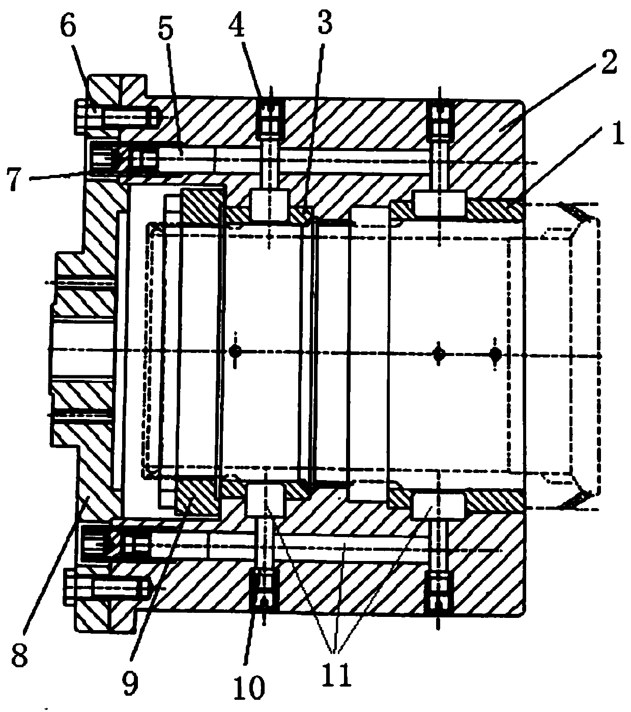
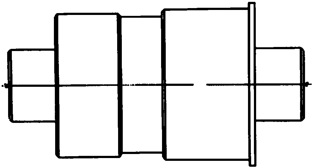
[0025] Such as Figure 1-2 Shown is a double-cylindrical pressurized rotor balancing fixture, including positioning bushing a1, balancing bushing 2, positioning bushing b3, screw a4, plunger 5, bolt 6, screw b7, adapter plate 8, and nut 9 and gasket 10;

[0026] The balance bushing 2 is in a sleeve shape, and the inner wall is provided with a plurality of installation grooves;

[0027] Fix the adapter plate 8 to the large end of the balance bushing 2 by bolts 6, and the adapter plate 8 is used for balanced rotation transmission;

[0028] The balance bushing 2 is provided with a positioning bushing a1 and a positioning bushing b3, forming a double cylinder;

[0029] The positioning bushing a1 and the positioning bushing b3 correspond to the positions of the radial installation grooves on the inner wall of the balance bushing 2 and are used for pressure clamping the front journal of the high pressure rotor; the positioning bushing a1 and the positioning bushing b3 and The high-pressur...


PUM


Abstract

The invention discloses a double-cylindrical-surface pressurizing type clamp for rotor balancing. The clamp comprises a positioning bushing a, a balancing bushing, a positioning bushing b, screws a, plungers, a bolt, screws b, an adapting plate, a nut and gaskets. The balancing bushing is in the shape of a sleeve, and a plurality of mounting grooves are formed in the inner wall of the balancing bushing. The adapting plate is fixed to the large end of the balancing bushing through the bolt, and the positioning bushing a and the positioning bushing b are arranged in the balancing bushing to formdouble cylindrical surfaces. The positioning bushing a and the positioning bushing b correspond to the mounting grooves in the radial direction of the inner wall of the balancing bushing in position.The plungers are poured into the mounting grooves in the radial direction of the inner wall of the balancing bushing. Each screw b is arranged at the upper end of the corresponding plunger, the nut is screwed on a part and clamped on the inner wall of the balancing bushing, and thus device movement is prevented. The inner wall of the balancing bushing is further provided with cavity channels communicating with the positioning bushing a and the positioning bushing b. The screws a penetrate through the outer wall of the balancing bushing and abut against the cavity channels. The gaskets are arranged between the screws a and the cavity channels. The cavity channels are filled with liquid plastic.

Description

Technical field [0001] The invention relates to the technical field of steel material supporting clamps for high-pressure rotor balancing, in particular to a double-cylinder pressurized rotor balancing clamp. Background technique [0002] The high-pressure rotor of the engine needs to be dynamically balanced. There is no direct support and contact between the part balancers, and the rotor shaft diameter is double-cylinder centering. The traditional tooling design requires the parts to be heated and assembled, and the room temperature must be restored after assembly. The problem of long cycle time and waste of energy, in addition, the surface of the machine part is scratched during the subassembly process of interference fit, especially the surface of the coating is easy to cause damage. Summary of the invention [0003] In order to solve the above technical problems, the purpose of the present invention is to provide a double-cylinder pressurized rotor balancing fixture. The speci...

Claims


Application Information

Patent Timeline
Patent Type & Authority Patents(China)
IPC IPC(8): B25B11/02
CPCB25B11/02
Inventor 杜立峰杨天南王景秋林东孙逍遥
Owner SHENYANG LIMING AERO-ENGINE GROUP CORPORATION
Why Eureka
Try Eureka