Vent cap for stabilizing internal pressure of speed reducer

A technology of internal pressure and reducer, which is applied in the field of vent caps, can solve the problems that vent caps cannot effectively take into account heat dissipation and oil leakage, and achieve the effects of avoiding oil leakage, reducing internal and external pressure differences, and reducing body temperature

Inactive Publication Date: 2018-02-27
江苏英太威机械设备工程有限公司
View PDF0 Cites 0 Cited by
  • Summary
  • Abstract
  • Description
  • Claims
  • Application Information

AI Technical Summary

Problems solved by technology

[0003] The technical problem to be solved by the present invention is: in order to solve the two problems that the existing vent cap cannot effectively take into account heat dissipation and oil leakage, the present invention provides a vent cap for stabilizing the internal pressure of the reducer. A vent pipe is installed to connect the inside of the reducer with the outside world, which is conducive to dissipating the heat in the reducer and effectively avoiding oil leakage.

Method used


Image

  • Vent cap for stabilizing internal pressure of speed reducer

Examples


Embodiment Construction

[0013] The present invention is described in further detail now in conjunction with accompanying drawing. These drawings are all simplified schematic diagrams, which only illustrate the basic structure of the present invention in a schematic manner, so they only show the configurations related to the present invention.

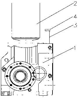
[0014] like figure 1 As shown, a breather cap for stabilizing the internal pressure of the reducer includes a reducer case 1 and a motor 2, the motor 2 is vertically installed on the upper surface of the reducer case 1, and the upper surface of the reducer case 1 is installed with a Connected vent pipe 3.

[0015] In a specific embodiment, the ventilation pipe 3 is located on a side away from the motor 2 .

[0016] In a specific embodiment, the vent pipe 3 is also provided with a dustproof cap 4 .

[0017] Preferably, the height of the ventilation pipe 3 is not less than 10 cm, and 15 cm is selected in this specific embodiment.

[0018] When in use, the du...


PUM


Abstract

The invention relates to the technical field of reducers, in particular to a breather cap for stabilizing the internal pressure of the reducer, which includes a reducer casing and a motor, the motor is vertically installed on the upper surface of the reducer casing, and the upper surface of the reducer casing is installed with a Air pipe connecting the inside of the machine with the outside world. The invention provides a vent cap for stabilizing the internal pressure of the reducer. A vent pipe connecting the inside of the reducer with the outside is installed on the upper surface of the reducer casing, which is beneficial to dissipate the heat in the reducer and can effectively avoid oil leakage the occurrence of the phenomenon.

Description

technical field [0001] The invention relates to the technical field of reducers, in particular to a breather cap for stabilizing the internal pressure of the reducer. Background technique [0002] As a common reducer for mechanical transmission equipment, the reducer is widely used in the fields of national defense, aerospace, construction, metallurgy and ore to reduce the speed and increase the torque. When the mechanism inside the reducer runs continuously, the internal temperature of the reducer will increase, causing the gas to expand. In order not to damage the dynamic oil seal of the reducer, a breather cap is installed on the reducer case, and the expansion gas is discharged through the breather cap, while reducing the temperature inside the reducer. However, when the mechanism in the reducer is running at high speed, it is easy to splash the lubricating oil, and the splashed lubricating oil often overflows from the vent cap, causing oil leakage from the reducer, whi...

Claims


Application Information

Patent Timeline
Patent Type & Authority Applications(China)
IPC IPC(8): F16H57/027F16H57/04
CPCF16H57/027F16H57/0416
Inventor 刘文昭
Owner 江苏英太威机械设备工程有限公司
Why Eureka
Try Eureka