Two-point correction method for uncooled infrared detector

An uncooled infrared and detector technology, applied in radiation pyrometry, instruments, measuring devices, etc., can solve problems such as large space noise and achieve the effect of improving imaging quality

Inactive Publication Date: 2018-02-27
BEIJING INST OF REMOTE SENSING EQUIP
View PDF3 Cites 10 Cited by
  • Summary
  • Abstract
  • Description
  • Claims
  • Application Information

AI Technical Summary

Problems solved by technology

[0004] The purpose of this method is to provide a two-point calibration method for uncooled infrared detectors in field tests, and to solve the problem that the single-point calibration with a single baffle in the past is too noisy in the test.

Method used


Image

  • Two-point correction method for uncooled infrared detector
  • Two-point correction method for uncooled infrared detector
  • Two-point correction method for uncooled infrared detector

Examples


Embodiment Construction

[0041] The specific steps of a two-point calibration method for an uncooled infrared detector are:

[0042] The first step is to build a two-point calibration system for uncooled infrared detectors

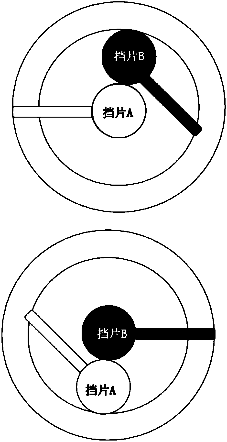
[0043] The two-point calibration system of the uncooled infrared detector includes: block A, block B, detector and output circuit module, block control module and FPGA data processing module.

[0044] The function of the detector and the output circuit module is to collect analog signals and convert them into digital signals.

[0045] The function of the baffle control module is to control the orderly appearance of baffles A and B in front of the detector glass window to obtain different radiation fluxes.

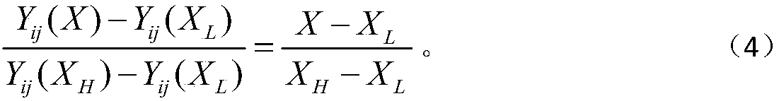
[0046] The function of the FPGA data processing module is to use the collected data to realize two-point non-uniform correction.

[0047] The second step: detector and output circuit module for signal acquisition and conversion

[0048] Collect the analog signal and convert ...


PUM


Abstract

The invention discloses a two-point correction method for an uncooled infrared detector. According to the method, two kinds of materials different in radiation rate are utilized as blocking pieces toconduct two-point correction on the detector. Firstly, a two-point correction system for the uncooled infrared detector is constructed, wherein the two-point correction system comprises the blocking piece A, the blocking piece B, the detector, an output circuit module, a blocking piece control module and an FPGA data processing module; secondly, the detector and the output circuit module are utilized to collect analog signals and convert the analog signals into digital signals; thirdly, the blocking piece control module is utilized to control the blocking piece A and the blocking piece B to appear in front of a glass window of the detector in order to obtain different radiation fluxes; finally, the FPGA data processing module is utilized to achieve two-point nonuniform correction through the utilization of collected data. By means of the method, the bias and gain of a photosensitive element of the detector are both compensated for, and the imaging quality is effectively improved.

Description

technical field [0001] The invention relates to a calibration method for an infrared detector, in particular to a two-point calibration method for an uncooled infrared detector. Background technique [0002] The detector assembly is a key component of the infrared thermal imaging camera, but its inherent non-uniformity seriously affects the imaging quality of the infrared imaging system. Since the uncooled infrared detector usually uses a black body for non-uniform correction, the scanning movement of the scanning mechanism makes the scene and the high and low temperature black body simultaneously imaged during imaging, and then the calculation of the correction coefficient is completed. It is difficult to use normally in the field test, and usually use a baffle for correction, resulting in unsatisfactory correction effect. Therefore, it is necessary to find a simple and convenient reference source to correct the response of the detector more reasonably. [0003] The metho...

Claims


Application Information

Patent Timeline
Patent Type & Authority Applications(China)
IPC IPC(8): G01J5/52
CPCG01J5/80G01J5/53
Inventor 刘玉姣李树林吕星煜彭明轩
Owner BEIJING INST OF REMOTE SENSING EQUIP
Why Eureka
Try Eureka