A split type low power consumption small auto focus brake

An auto-focusing, low-power technology, applied in instruments, installations, optics, etc., can solve the problems of debris contaminating the surface of the image sensor, multi-image noise of the image sensor, affecting the accuracy of auto-focusing, etc., to achieve light weight, clear images, The effect of low power consumption

Active Publication Date: 2020-06-23
VISTA INNOTECH LTD
View PDF3 Cites 0 Cited by
  • Summary
  • Abstract
  • Description
  • Claims
  • Application Information

AI Technical Summary

Problems solved by technology

[0010] An object of the present invention is to provide a split-type low-power small-sized auto-focus brake to solve the problem of nonlinear friction generated by the limit structure of the sensor-movable actuator in the prior art during the auto-focus process, which affects the auto-focus accuracy problem
[0011] Another object of the present invention is to provide a split-type low-power small-sized autofocus brake to solve the problem of fragments and image contamination caused by friction or impact in the actuator when the brake is dropped or during the autofocus process in the prior art Problems with the sensor surface
[0012] Another object of the present invention is to provide a split-type low-power small auto-focus brake to solve the problem of poor heat dissipation of the sensor movable actuator in the prior art, and the image sensor will have a lot of image noise and even cannot work normally. question

Method used


Image

  • A split type low power consumption small auto focus brake
  • A split type low power consumption small auto focus brake
  • A split type low power consumption small auto focus brake

Examples


Embodiment Construction

[0040] In order to make the object, technical solution and advantages of the present invention clearer, the implementation manner of the present invention will be further described in detail below in conjunction with the accompanying drawings.

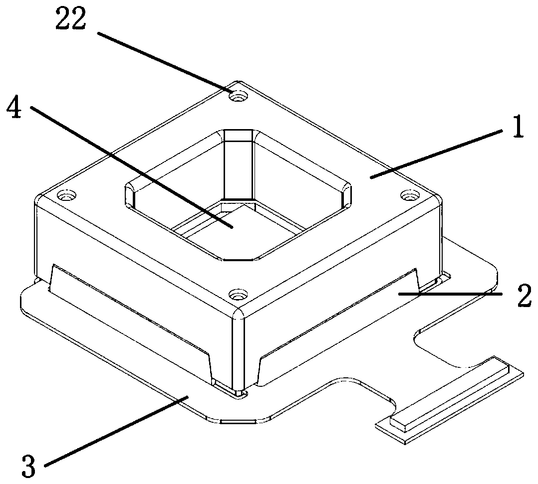
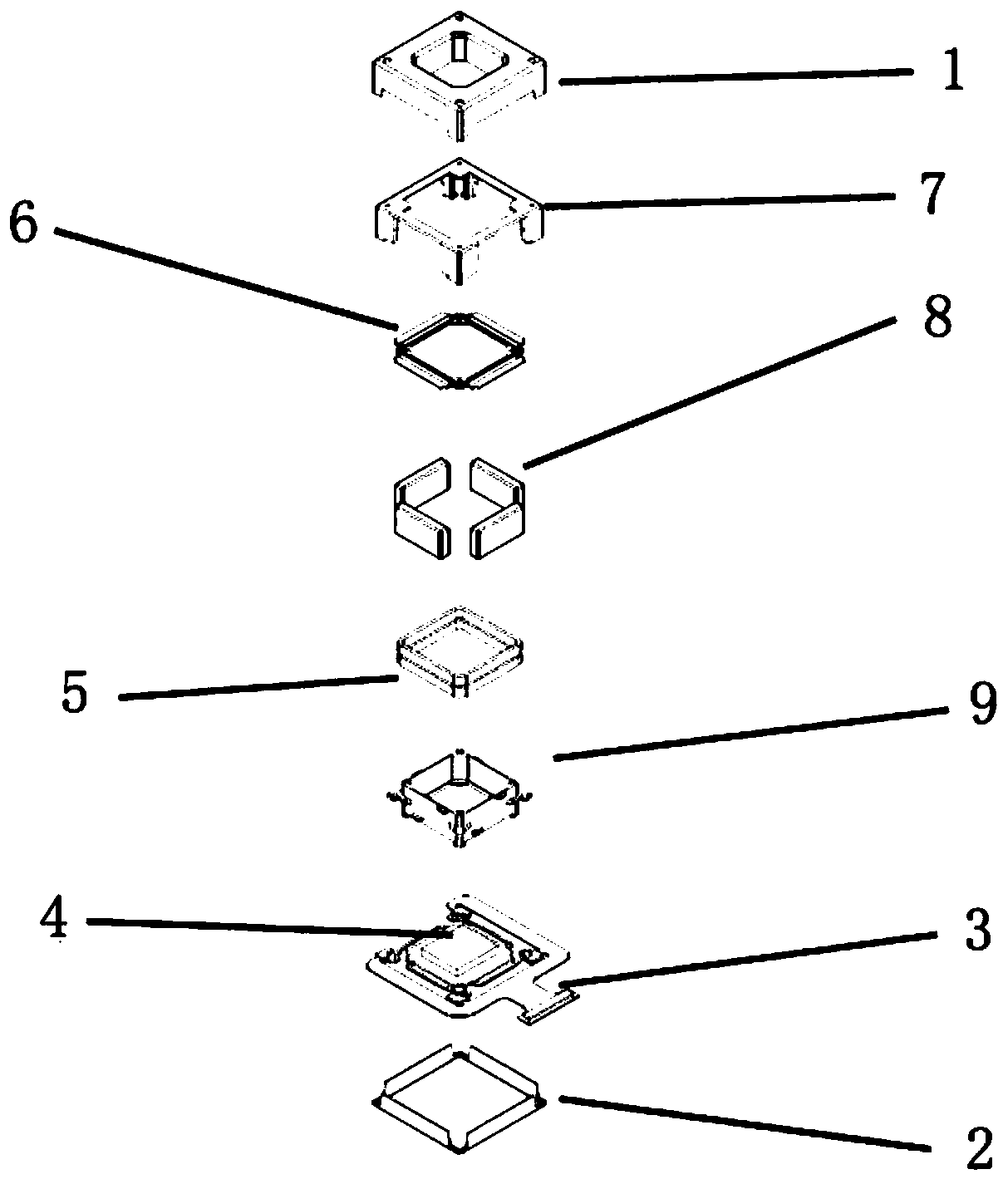
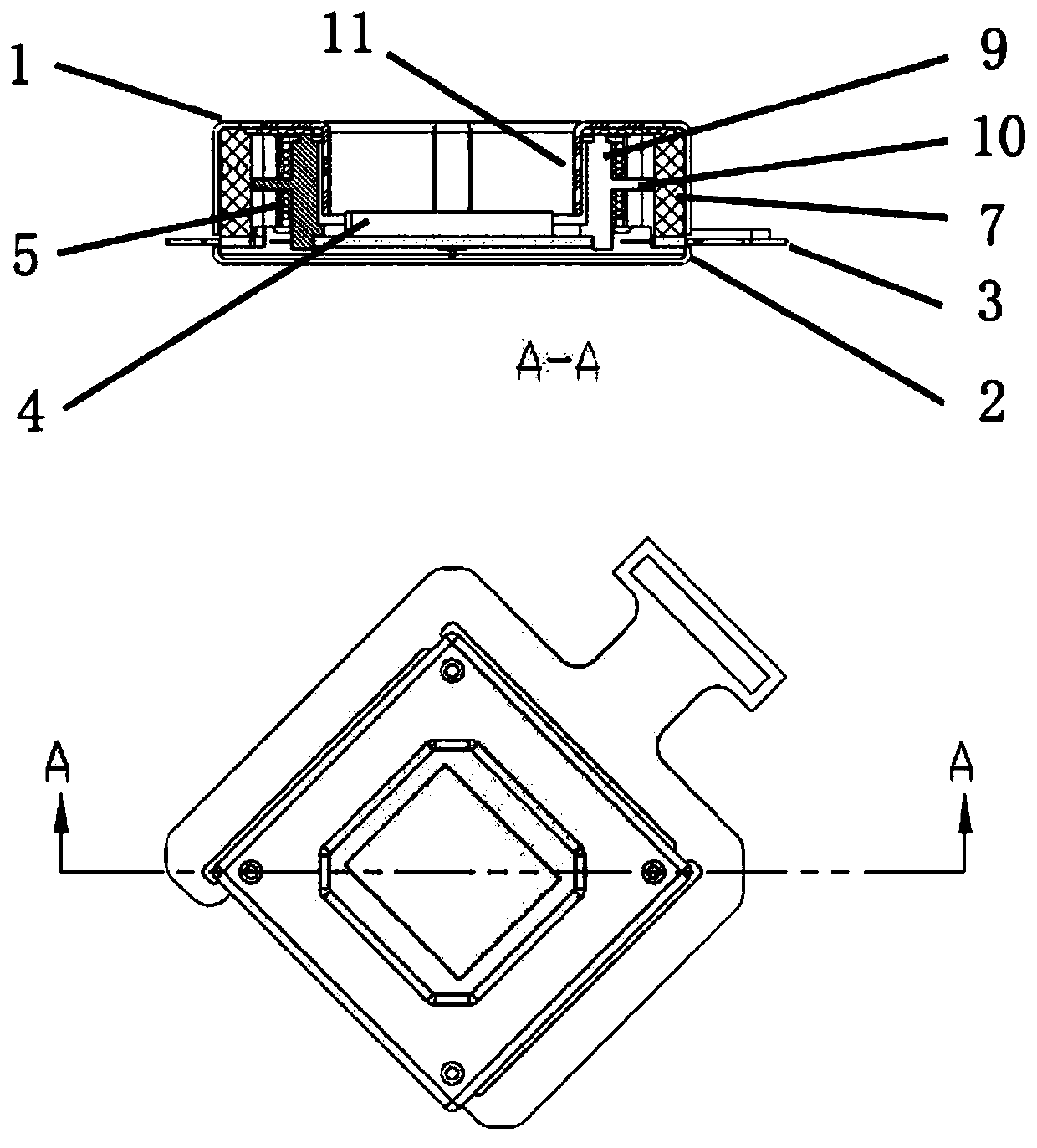
[0041] An embodiment of the present invention provides a split-type low-power small autofocus brake, refer to Figure 1 to Figure 7As shown, it includes a housing, a spring, an image sensor carrier 9 , at least one magnet 8 , at least one independent coil 5 and an elastic circuit board 3 . The spring is arranged on the inner surface of the top of the housing, and can elastically deform along the vertical axis of the housing. Below the spring is an elastic circuit board 3 placed horizontally on the lower part of the housing. One end of the image sensor carrier 9 is connected to the spring, and the other end is connected to the elastic circuit board 3 , the surface of which is rigidly connected to the image sensor 4 , and the top of the ...


PUM


Abstract

The invention belongs to the technical field of camera brakes, and specifically relates to a split-type low-power small autofocus brake, which includes a housing, a spring, an image sensor carrier, at least one magnet, at least one independent coil, and an elastic circuit board, a spring, and an image sensor carrier . The elastic circuit board forms a spring vibrator system with one axis displacement degree of freedom. At least one magnet is arranged on the inner wall of the housing, and the independent coil is arranged on the image sensor carrier and correspondingly arranged with the magnet. Ampere's force acts on the magnetic field. The braking structure of the present invention does not generate nonlinear friction force, and has the characteristics of good dustproof and heat dissipation effects.

Description

technical field [0001] The invention belongs to the technical field of camera brakes, and in particular relates to a split-type low-power consumption small auto-focus brake. Background technique [0002] In recent years, portable camera devices with an autofocus function have become very popular and have basically become a standard function of the camera devices. When the subject is at different distances during the shooting process, the auto focus function can effectively improve the resolution of the closer subject in the image and improve the photo quality of the close-up. On the other hand, the autofocus function can blur the image of objects at other distances, making the subject stand out more in the photo. [0003] The traditional autofocus system achieves the effect of changing the optimal object distance (Optimal Object Distance) by moving the position of the entire lens or some lenses in the lens. In recent years, traditional mainstream actuators can precisely ch...

Claims


Application Information

Patent Timeline
Patent Type & Authority Patents(China)
IPC IPC(8): G02B7/09G02B7/28
CPCG02B7/09G02B7/282
Inventor 麦练智
Owner VISTA INNOTECH LTD
Why Eureka
Try Eureka