PCB clamping mechanism

A technology of PCB board and clamping mechanism, which is applied in the direction of measuring devices, instruments, and optical devices, etc., can solve the problems of inconvenient loading and unloading of PCB boards, affect the detection structure, and reduce work efficiency, so as to achieve simple structure and ensure the shooting of images , the effect of improving work efficiency

Inactive Publication Date: 2009-12-23
SUZHOU MINGFU AUTOMATIC SCI & TECH
View PDF0 Cites 14 Cited by
  • Summary
  • Abstract
  • Description
  • Claims
  • Application Information

AI Technical Summary

Problems solved by technology

Usually, the mechanism used to clamp the PCB on the testing equipment is either poor in clamping stability, and the PCB board is prone to slight displacement during the testing process, t

Method used


Image

  • PCB clamping mechanism
  • PCB clamping mechanism
  • PCB clamping mechanism

Examples


Example Embodiment

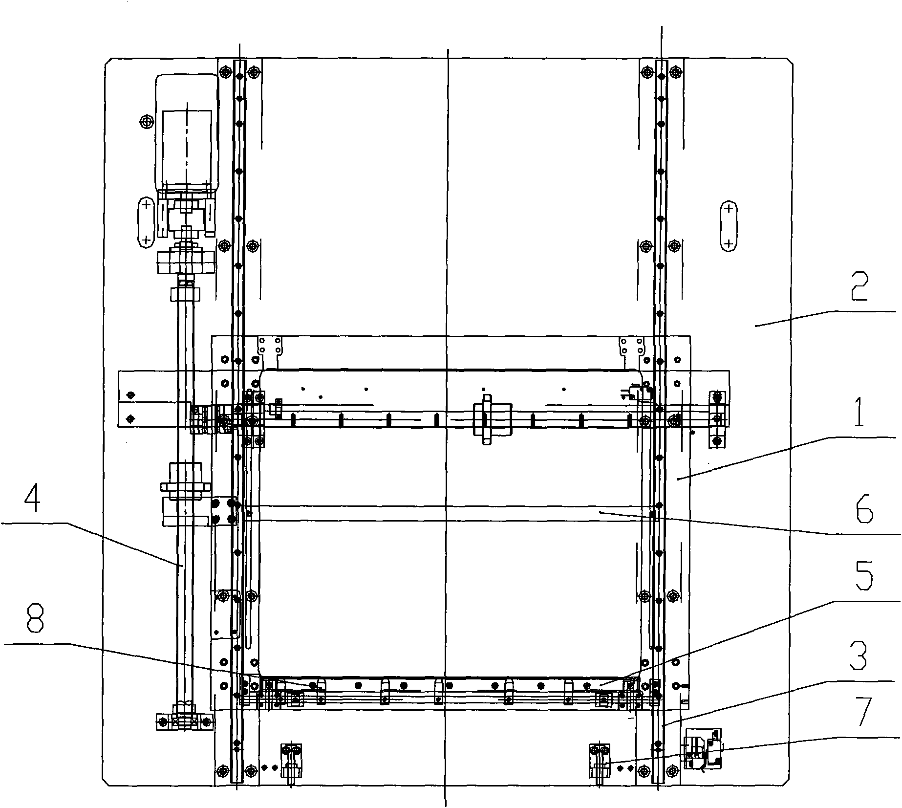
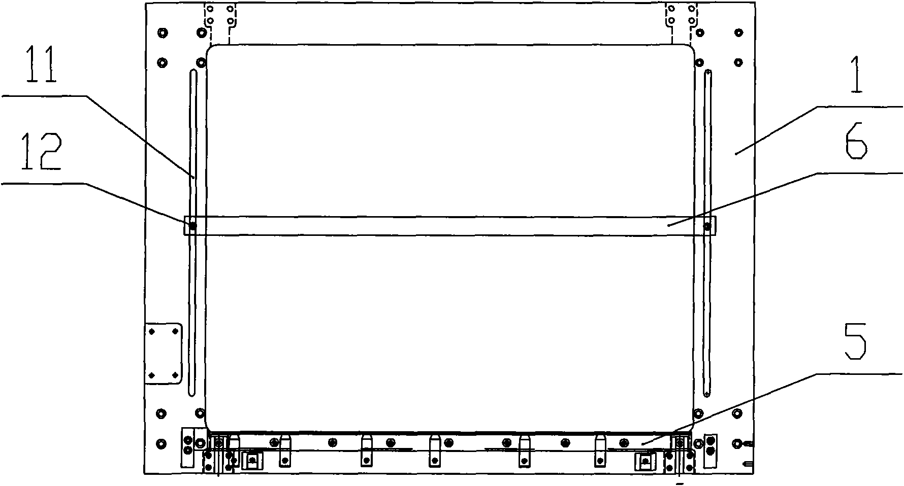
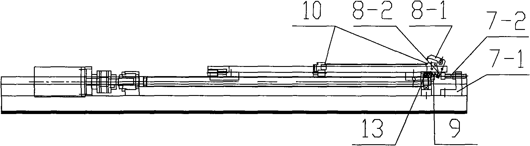
[0016] like figure 1 , figure 2 A PCB board clamping mechanism shown has a fixed base 1, the fixed base 1 is arranged on the guide rail 3 of the machine base 2, and a wire for driving the fixed base 1 to move back and forth on the guide rail 3 is provided on one side of the fixed base 1. Rod 4 is provided with a PCB board clamping mechanism on the fixed seat 1, and the PCB board clamping mechanism includes a front stop bar 5 and a rear stop bar 6 which are horizontally mounted on the fixed seat 1 and a rear stop bar 6 which is fixedly installed on the machine base 2 The ejector rod device 7, the front stop bar 5 is fixedly connected with the fixed seat 1, the rear stop bar 6 is slidably connected with the fixed seat 1, and at least one clamp 8 is pinned on the front stop bar 1, such as image 3 As shown, the clamp 8 is composed of a chuck 8-1 arranged above the front bar 5 and a top block 8-2 arranged below the front bar 5, and a spring 9 is arranged below the front bar 5, ...


PUM

PropertyMeasurementUnit
Inclinationaaaaaaaaaa

Abstract

The invention relates to a PCB detection device, in particular to a PCB clamping mechanism during detection. The PCB clamping mechanism is provided with a fixed seat; the fixed seat is arranged on a guide rail of an engine base; one side of the fixed seat is provided with a screw rod for driving the fixed seat to move forward and backward on the guide rail; the PCB clamping mechanism is arranged on the fixed seat; a front retainer is fixedly connected with the fixed seat and a back retainer is slidably connected with the fixed seat; the front retainer is in pin connection with at least one fixture; the fixture consists of a chuck arranged above the front retainer and a top block arranged below the front retainer; a spring is arranged below the front retainer and is pressed against the top block; and a post rod mechanism is pressed against the top block when the fixed seat is moved to the top front end along the guide rail. The PCB detection device is simple in structure, and can conveniently and quickly perform fixture on a PCB, and improves the working efficiency; meanwhile, the PCB fixture has comparatively stable fixture on the PCB, and ensures the distinct capture images of a camera on the PCB so as to improve the accuracy of PCB detection.

Description

technical field [0001] The invention relates to a PCB board detection device, in particular to a clamping mechanism for PCB board detection. Background technique [0002] Usually, when inspecting the PCB board, it is necessary to clamp and fix the PCB board, and then use the camera to shoot the PCB board and compare it with the pre-stored information in the computer, so as to detect the installation position of the electronic components on the PCB the goal of. Usually, the mechanism used to clamp the PCB on the testing equipment is either poor in clamping stability, and the PCB board is prone to slight displacement during the testing process, thereby affecting the testing structure, or the clamping mechanism is relatively complicated, and the loading and unloading of the PCB board is not convenient, reducing the work efficiency. Contents of the invention [0003] In order to overcome the above-mentioned shortcomings of the clamping mechanism when fixing the PCB, the pres...

Claims


Application Information

Patent Timeline
IPC IPC(8): G01B11/00
Inventor 庄春明
Owner SUZHOU MINGFU AUTOMATIC SCI & TECH
Why Eureka
Try Eureka