Continuous steel plate punching device

A technology of punching and equipment, applied in the direction of launching equipment, metal processing equipment, piercing tools, etc., can solve problems that plague the normal production, frequent replacement of punches, and affect the production process, so as to save manpower, save labor, and improve use. The effect of longevity

Active Publication Date: 2018-03-02
YUEXI COUNTY YONGTAI MACHINERY MFG
View PDF9 Cites 3 Cited by
  • Summary
  • Abstract
  • Description
  • Claims
  • Application Information

AI Technical Summary

Problems solved by technology

[0002] As the market has higher and higher requirements for vehicle lightweight and safety, the application of ultra-high-strength steel plates in vehicles is also increasing. The existing truck beam punching equipment is not designed to take into account repeated punching during high-speed continuous punching. The instantaneous high temperature has a great impact on the punch, which leads to a large number of punch breakage problems in the process of producing high-st

Method used


Image

  • Continuous steel plate punching device
  • Continuous steel plate punching device
  • Continuous steel plate punching device

Examples


Embodiment Construction

[0018] The following will clearly and completely describe the technical solutions in the embodiments of the present invention with reference to the accompanying drawings in the embodiments of the present invention. Obviously, the described embodiments are only some, not all, embodiments of the present invention. Based on the embodiments of the present invention, all other embodiments obtained by persons of ordinary skill in the art without making creative efforts belong to the protection scope of the present invention.

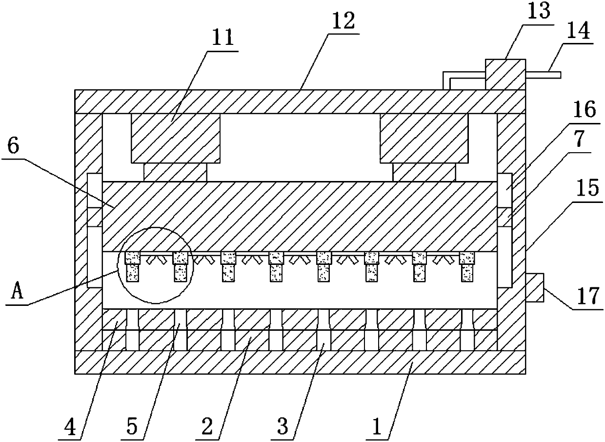
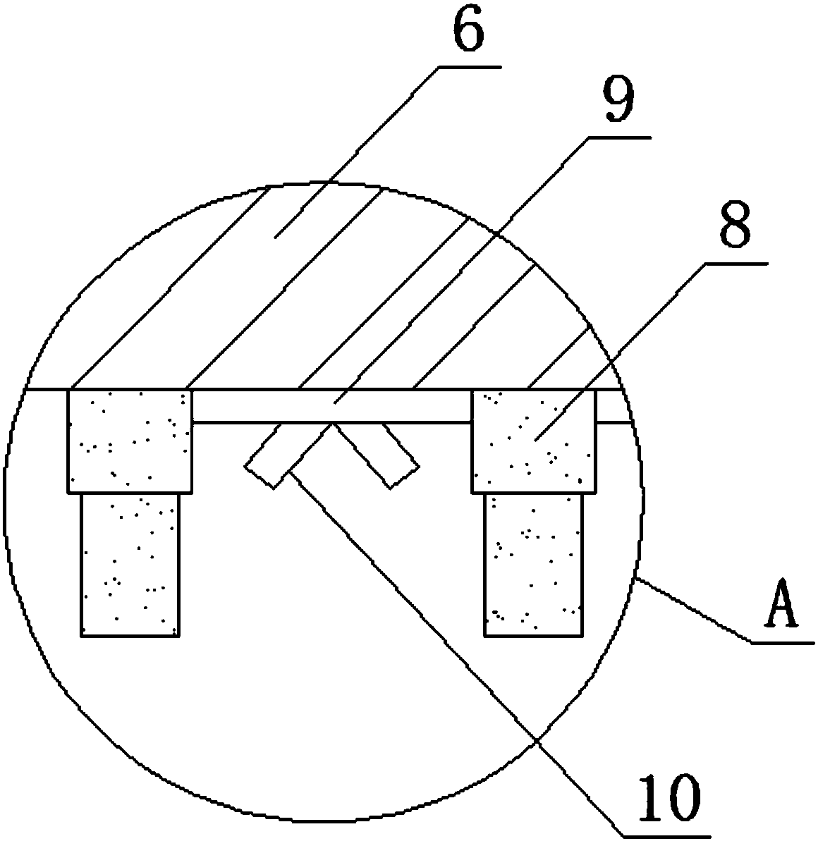
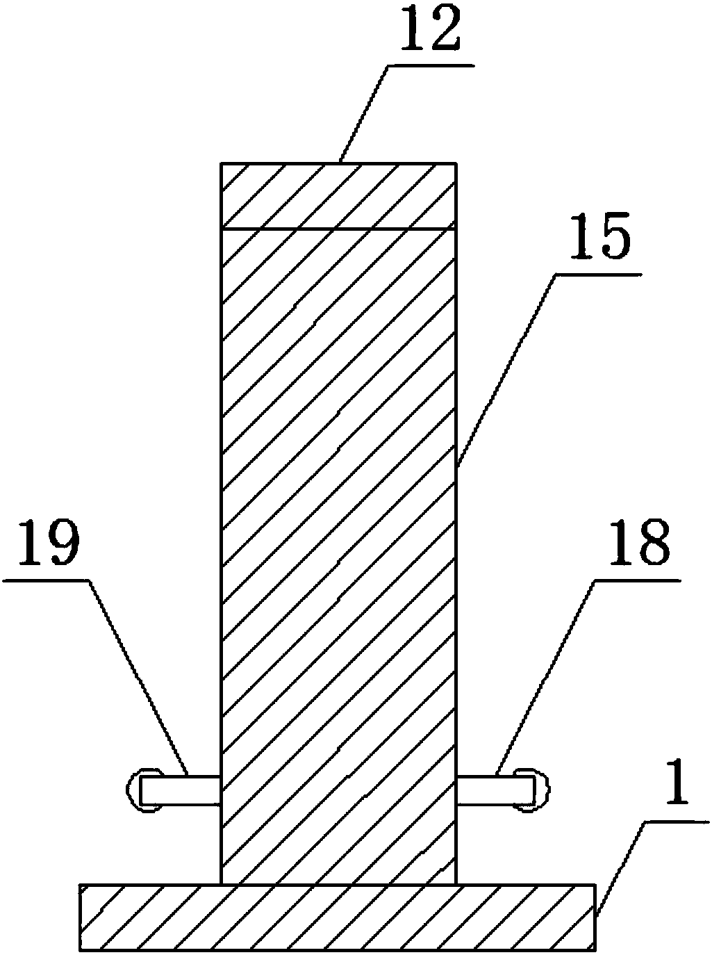
[0019] The present invention provides such Figure 1-5 The shown continuous punching equipment for steel plates includes a bottom plate 1, a fixed block 2 is arranged on the top of the bottom plate 1, a discharge groove 3 is arranged between the fixed blocks 2, and a lower mold is arranged on the top of the fixed block 2 4. The lower mold 4 is provided with a punching hole 5, the top of the lower mold 4 is provided with an upper mold 6, the two sides of the up...


PUM


Abstract

The invention discloses a continuous steel plate punching device comprising a base plate. Fixing blocks are arranged on the top of the base plate. Material discharging grooves are formed between the fixing blocks. A lower die is arranged on the tops of the fixing blocks. The lower die is provided with punching holes in a penetrated manner. An upper die is arranged on the top of the lower die. Thetwo sides of the upper die are provided with sliding blocks. The bottom of the upper die is provided with punch pins. Cooling water pipes are arranged between the punch pins. The bottoms of the cooling water pipes are provided with sprayers. The top of the upper die is provided with air cylinders. The tops of the air cylinders are provided with a top plate. One end of the top of the top plate is provided with a booster pump. The booster pump is provided with a water source connection pipe. The two ends of the bottom of the top plate are both provided with side plates. According to the continuous steel plate punching device, an auxiliary feeding device, a cross rod and separating blocks are arranged, so that labor is greatly saved, the burden on operation personnel is lowered, high practicability is achieved, the work efficiency is effectively improved, a steel plate can be prevented from getting stuck in the discharging process, and the fault rate is lowered.

Description

technical field [0001] The invention relates to the technical field of punching equipment, in particular to continuous punching equipment for steel plates. Background technique [0002] As the market has higher and higher requirements for vehicle lightweight and safety, the application of ultra-high-strength steel plates in vehicles is also increasing. The existing truck beam punching equipment is not designed to take into account repeated punching during high-speed continuous punching. The instantaneous high temperature has a great impact on the punch, which leads to a large number of punch breakage problems in the process of producing high-strength steel plates, resulting in frequent replacement of punches, seriously disturbing the normal production, not only causing high maintenance costs, but also seriously affecting The production process cannot meet the requirements of future product lightweight for high-strength steel plate processing technology. At the same time, whe...

Claims


Application Information

Patent Timeline
IPC IPC(8): B21D28/26B21D28/34B21D37/16B21D45/02B21D43/02
CPCB21D28/26B21D28/34B21D37/16B21D43/02B21D45/02
Inventor 余方成
Owner YUEXI COUNTY YONGTAI MACHINERY MFG
Why Eureka
Try Eureka