Garbage compression processing station and garbage processing method

A technology of garbage compression and treatment station, applied in the direction of presses, punching machines, manufacturing tools, etc., can solve the problems of low degree of automation, labor-intensive, large exhaust gas inhalation, etc., and achieves high intelligence strength, reasonable overall design, and convenient management. Effect

Pending Publication Date: 2018-03-02
FUJIAN YONGZHI MACHINERY EQUIP
View PDF7 Cites 3 Cited by
  • Summary
  • Abstract
  • Description
  • Claims
  • Application Information

AI Technical Summary

Problems solved by technology

The working methods of the existing garbage stations and garbage compression devices are relatively traditional, and the degree of automation is low. Operators need to enter the garbage station for operation. This will cause the staff who have been in the garbage station for a long time to inhale a large amount of exhaust gas, which will easily lead to Physical discomfort and even occupational diseases
[0003] At the same time, the compression device is used in the garbage station to carry out the compression process. During the garbage compression process, it is usually difficult to complete the compression process once. The traditional garbage compression device usually requires the operator to carry out multiple compression operations and check whether the compression is qualified. forward
There are also problems of low degree of automation and labor-intensive

Method used


Image

  • Garbage compression processing station and garbage processing method
  • Garbage compression processing station and garbage processing method
  • Garbage compression processing station and garbage processing method

Examples


Embodiment Construction

[0013] The present invention is further illustrated by the following examples:

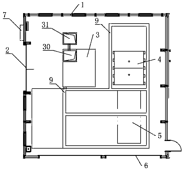
[0014] refer to figure 1 , a garbage compression treatment station, comprising an external wall 1, a feed door 2 is provided on one side of the wall 1, a pit 3 is provided on the inner side of the feed gate 2, and a garbage compression device 4 is provided on one side of the pit 3 . The bottom of the pit 3 is inclined to one side, and a settling well 30 is provided at the lowest point thereof, and the settling well 30 is connected to a water collection well 31 provided outside the pit 3 . In the garbage compression device 4, a garbage exchange position 5 is provided on the side of the garbage outlet, and a discharge door 6 is provided on one side wall 1 of the garbage exchange position 5, and a drain is provided on the peripheral bottom surface of the garbage compression device 4 and the garbage exchange position 5. Groove9. A controller 7 provided on the outside of body of wall 1 .

[0015] r...


PUM


Abstract

The invention discloses a garbage compression processing station comprising an external wall body. A feeding port is formed in one side of the wall body; a ground pit is formed in the inner side of the feeding port; one side of the ground pit is provided with a garbage compression device; a garbage exchanging position is formed in one side of a garbage outlet of the garbage compression device; a controller controlling the garbage compression device is arranged on the external side of the wall body; the garbage compression device has a rack, a garbage case disposed in the rack and a compressionmechanism arranged over the garbage case; the garbage compression device further has a shoveling bucket arranged in front of the rack; the compression mechanism is formed by a pressurizing flat platecapable of vertically moving and a hydraulic piston rod arranged over the pressurizing flat plate; and the compression mechanism is provided with a pressure sensor sensing pressure applied to the pressurizing flat plate and a displacement sensor sensing vertical displacement of the pressurizing flat plate. The garbage compression processing station has great automation degree, is safe and clean,and easy to operate.

Description

technical field [0001] The invention relates to garbage treatment technology, in particular to a garbage compression treatment station and a garbage treatment method thereof. Background technique [0002] A large amount of garbage is generated in production and life, and these garbage are usually first transported to the garbage station for preliminary treatment, and then transferred for recycling. The working methods of the existing garbage stations and garbage compression devices are relatively traditional, and the degree of automation is low. Operators need to enter the garbage station for operation. This will cause the staff who have been in the garbage station for a long time to inhale a large amount of exhaust gas, which will easily lead to Physical discomfort can even lead to occupational diseases. [0003] At the same time, the compression device is used in the garbage station to perform compression processing. In the process of garbage compression, it is usually di...

Claims


Application Information

Patent Timeline
Patent Type & Authority Applications(China)
IPC IPC(8): B30B1/34B30B15/30B30B15/16B30B15/22B30B15/32B30B15/00B09B3/00
CPCB09B3/00B30B1/34B30B15/0052B30B15/16B30B15/22B30B15/30B30B15/32
Inventor 吴厚雷
Owner FUJIAN YONGZHI MACHINERY EQUIP
Why Eureka
Try Eureka