
Oil suction device, engine and vehicle

A technology of engine and oil suction pipe, which is applied in the direction of engine components, engine lubrication, lubricant conduit device, etc., can solve the problems of dry friction, cavitation, cavitation, etc., and achieve the effect of preventing cavitation

Pending Publication Date: 2018-03-02
昆山三一动力有限公司
View PDF0 Cites 5 Cited by
  • Summary
  • Abstract
  • Description
  • Claims
  • Application Information

AI Technical Summary

Problems solved by technology

[0003] The oil inlet chamber of the oil pump is provided with an oil suction device. One end of the oil suction device is fixedly connected with the oil inlet chamber. The oil suction device sucks the oil in the oil pan into the oil cavity, but when the engineering equipment works at an inclined angle, the oil level of the engine oil pan also inclines accordingly, and the inclination angle is too large, such as when it exceeds 30° The requirement of 30° may prevent the oil suction end of the oil suction device from being immersed in the engine oil. At this time, the equipment continues to work, and part of the air is sucked into the oil pump through the oil suction device, resulting in cavitation, which will accelerate the wear of the gears of the oil pump. At the same time, the lubricating parts of the engine Dry friction due to poor lubrication can cause the engine to burn the bearing bush in severe cases
[0004] In order to reduce or avoid the phenomenon of cavitation, it is generally used to add baffles to the oil pan or adopt a cylindrical oil suction device. Although the above solutions can reduce the occurrence of cavitation to a certain extent, when the oil level When the inclination angle exceeds the controllable range, the air suction phenomenon will also occur

Method used


Image

  • Oil suction device, engine and vehicle
  • Oil suction device, engine and vehicle
  • Oil suction device, engine and vehicle

Examples


Embodiment Construction

[0032] It should be noted that, in the case of no conflict, the embodiments of the present invention and the features in the embodiments can be combined with each other. The present invention will be described in detail below with reference to the accompanying drawings and examples.

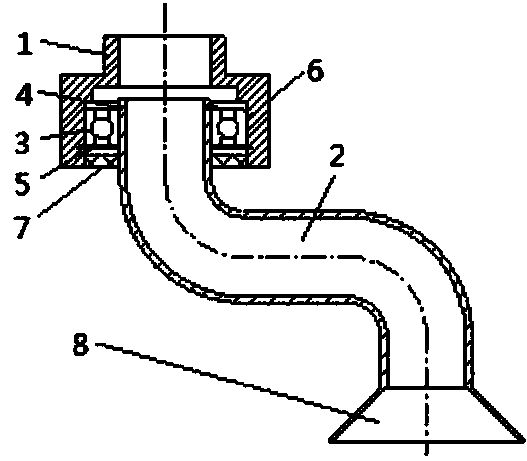
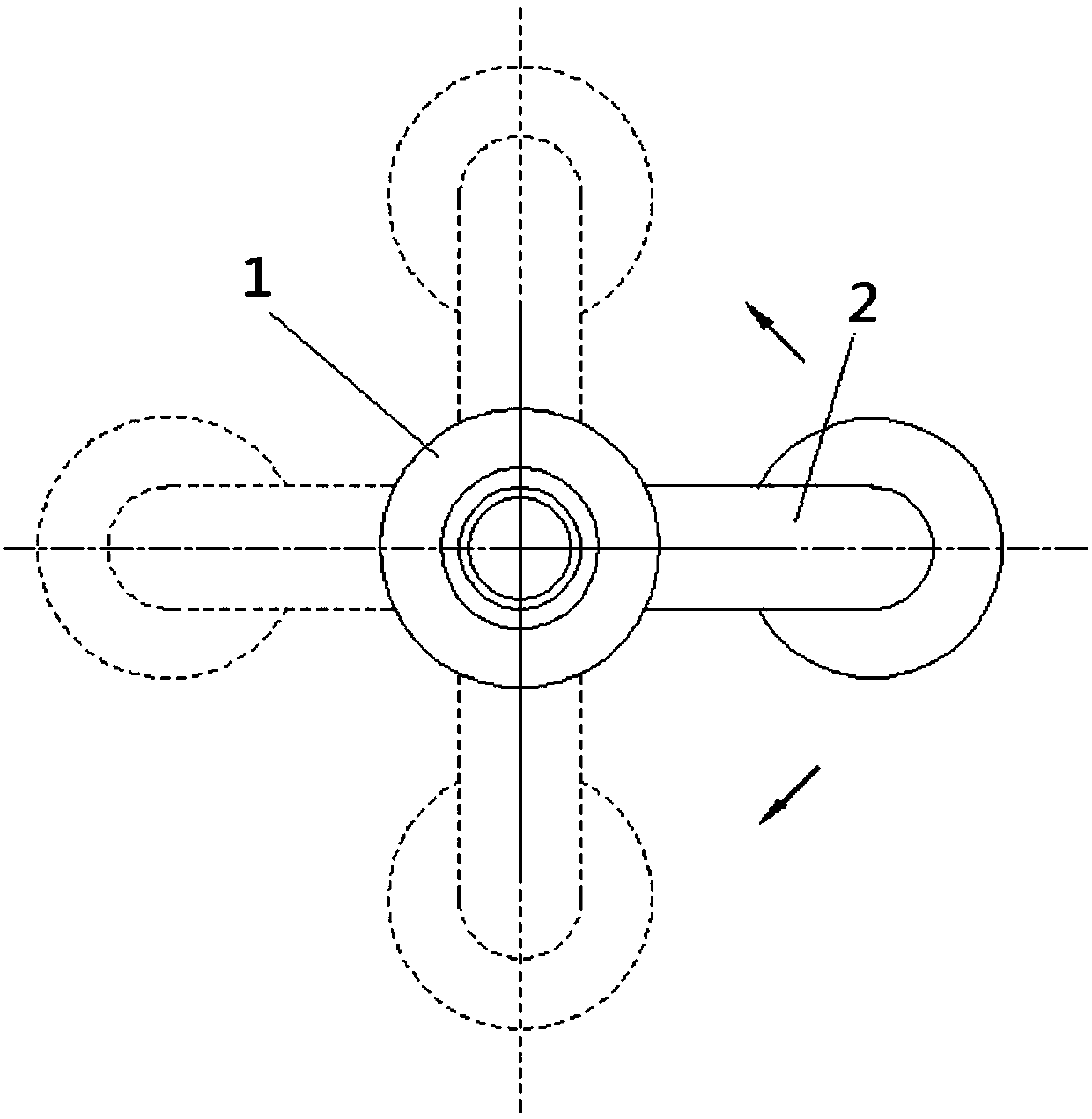
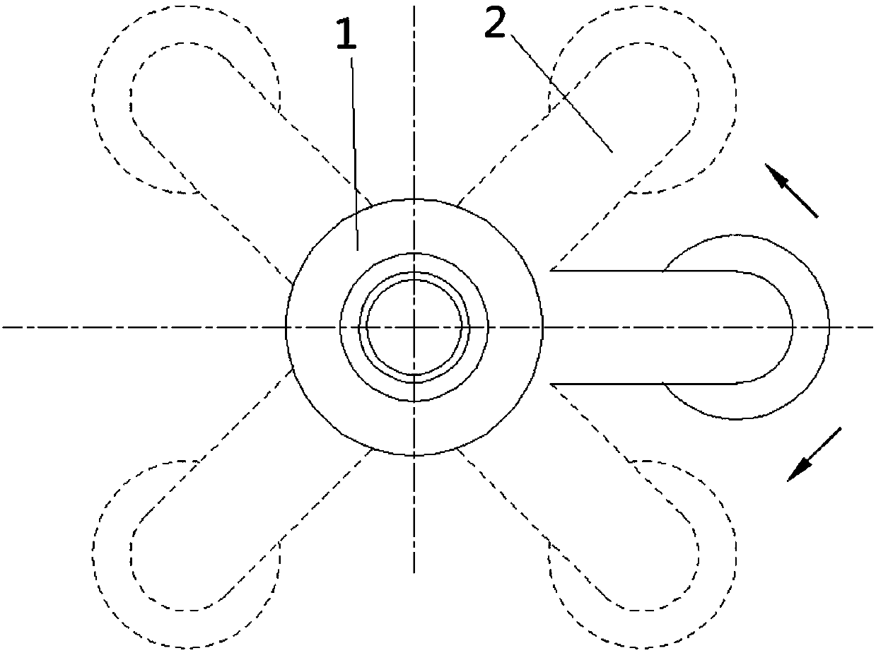
[0033] The gist of the present invention utilizes the gravitational effect, considering that the gravitational factor is the main reason for the change of the oil level in the engine oil pan, so the oil suction pipe can also be changed according to the gravitational factor to ensure that the oil suction end of the oil suction pipe is in the oil pan. It can be submerged below the oil level at a certain inclination angle. Specifically, when the inclination angle of the engine changes, the oil suction pipe will follow the action of its own gravity and automatically adapt to the change of the oil liquid level in the engine oil pan to ensure the oil suction of the oil suction pipe. The end can always ...


PUM


Abstract

The invention provides an oil suction device comprising a connecting shell and an oil suction pipe. One end of the oil suction pipe is connected with the connecting shell, the other end of the oil suction pipe serves as the oil suction end, and the oil suction end of the oil suction pipe moves in a following mode under the gravity effect. The position of the oil suction pipe of the oil suction device can be changed based on the gravity factor so as to guarantee that the oil suction end of the oil suction pipe can be immersed under the liquid level of engine oil at a certain dip angle of an oilbottom shell, specifically, when the dip angle of an engine is changed, the oil suction pipe moves in the following mode under the gravity effect so as to automatically adapt to the liquid level change of the engine oil in the oil bottom shell of the engine, it is guaranteed that the oil suction end of the oil suction pipe can be immersed into the engine oil all the time, the oil suction device is prevented from sucking air, and the situation that lubricating parts of the engine are well lubricated is guaranteed. The invention provides the engine provided with the oil suction device and a vehicle provided with the engine on the other hand.

Description

technical field [0001] The invention relates to the technical field of engines, in particular to an oil absorbing device, an engine and a vehicle. Background technique [0002] There is an oil pump inside the engine. The function of the oil pump is to increase the oil to a certain pressure and then forcefully send it to the moving surfaces of the various parts of the engine to lubricate the various parts of the engine. Its working principle is: when the engine is working, the driving gear on the camshaft drives the transmission gear of the oil pump, so that the driving gear fixed on the driving gear shaft rotates, thereby driving the driven gear to rotate in the opposite direction, and the oil is pumped from the inlet The oil chamber is sent to the oil outlet chamber along the tooth gap and the pump wall. In this way, a low pressure is formed at the oil inlet chamber to generate suction, and the oil in the oil pan is sucked into the oil chamber. Due to the continuous rotat...

Claims


Application Information

Patent Timeline
Patent Type & Authority Applications(China)
IPC IPC(8): F01M11/02
CPCF01M11/02F01M2011/007
Inventor 李昊钱汉生陈少华
Owner 昆山三一动力有限公司
Learn More