Cleaning head for camera cleaning device

A technology of cleaning device and cleaning head, applied in the field of cleaning head, can solve the problems of labor, long operation time, time-consuming and the like

Pending Publication Date: 2018-03-06
夏德明
View PDF5 Cites 7 Cited by
  • Summary
  • Abstract
  • Description
  • Claims
  • Application Information

AI Technical Summary

Problems solved by technology

[0002] At present, outdoor dust is flying all over the sky, especially high-altitude cameras on highways need to be cleaned every 20-30 days to have a clear picture, but the current cleaning method is to use stairs and engineering vehicles to lift people to a height of 6-7 meters for cleaning, and the working time Long, affecting traffic, time-consuming, laborious

Method used


Image

  • Cleaning head for camera cleaning device
  • Cleaning head for camera cleaning device
  • Cleaning head for camera cleaning device

Examples


Embodiment 1

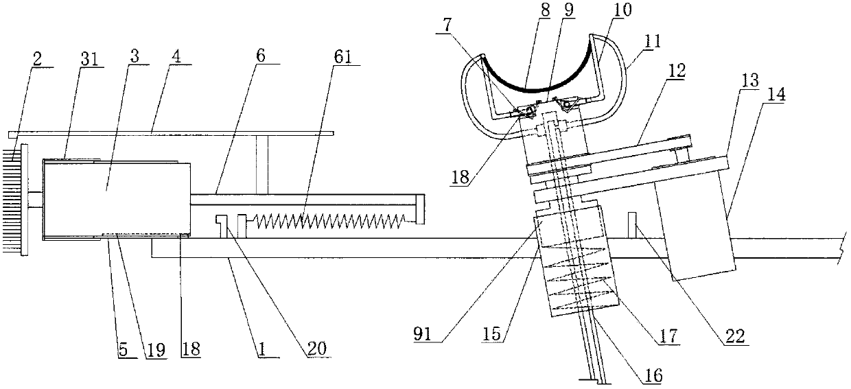
[0029] Such as figure 1 , Figure 5-Figure 7 A cleaning head for a camera cleaning device shown includes a connecting arm 1, which is provided with a spherical camera cleaning mechanism; the spherical camera cleaning mechanism includes a mounting seat 9 driven by a first drive motor 14, and the mounting seat A support 91 is arranged below 9, and the support 91 is connected with the connecting arm 1, and the first drive motor 14 is connected with the support 91 through a bracket 13; the mounting base 9 can rotate relative to the support 91. The mounting base 9 is movably connected with the connecting arm 1; at least a pair of cleaning tape brackets 10 are arranged on the mounting base 9, and flexible cleaning material is provided on the surface of the cleaning tape. Cleaning belt 8 is arranged between cleaning belt support 10; The connecting end 102 of cleaning belt support 10 and mounting base 9 is provided with the torsion spring 18 as reset mechanism, and mounting base 9 is...

Embodiment 2

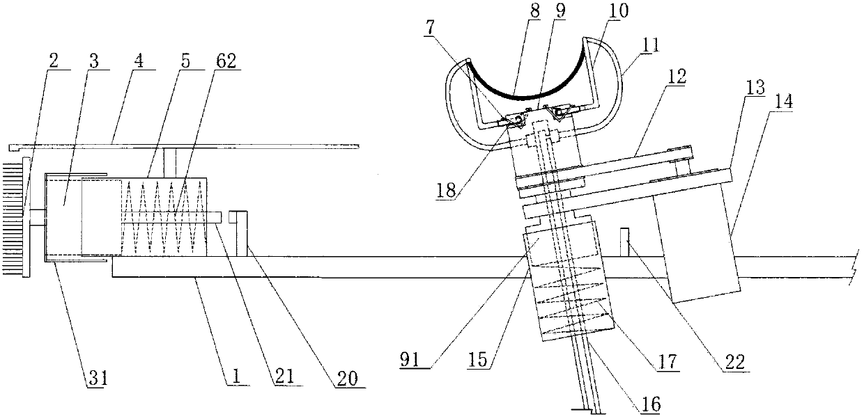
[0036] On the basis of Example 1, such as figure 2 As shown, the second driving motor 3 is arranged in a motor sleeve 5 , and a return spring 62 is arranged between the second driving motor 3 and the motor sleeve 5 . When the contact force between the cleaning head 2 and the surface of the camera is too large, the return spring 62 is compressed to store force, and when the contact force becomes smaller, the second driving motor 3 together with the cleaning head 2 moves to the initial position under the action of the spring force.

[0037] Such as figure 2 As shown, as an improved solution, a limit switch 20 is provided on the connecting arm 1, and a contact rod 21 is provided at the rear of the second driving motor 3. The contact rod 21 passes through the rear of the motor sleeve 5 and is aligned with the limit switch. bit switch 20. The limit switch 20 is connected with a mechanism for controlling the multi-directional movement of the connecting arm 1. This mechanism can ...

Embodiment 3

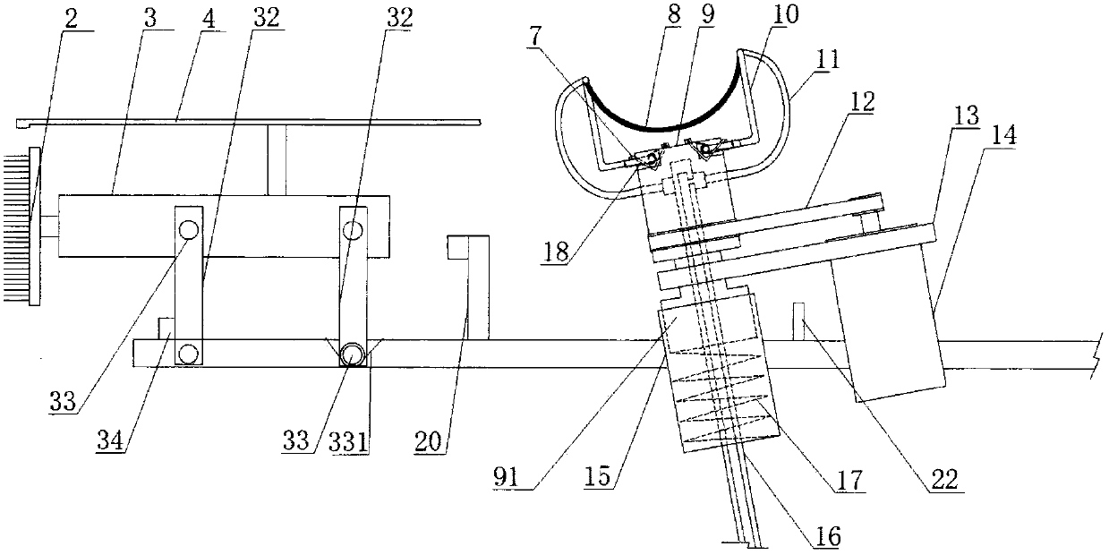
[0040] On the basis of Example 1, such as image 3 As shown, the second drive motor 3 is hinged to the connecting arm 1 through two vertical connecting rods 32 , and shafts 33 are arranged at the hinges, and a reset torsion spring 331 is arranged on one of the shafts 33 . A block 34 for blocking the vertical link 32 and limiting its initial position is also arranged on the connecting arm 1 .

[0041] Such as image 3 As shown, as an improved solution, a limit switch 20 is set on the connecting arm 1, the limit switch 20 is located behind the second drive motor 3, and the limit switch 20 is connected to a mechanism for controlling the multidirectional movement of the connecting arm 1. The mechanism of the prior art can be adopted, and the purpose is to realize the control of the front and rear, left and right and up and down movements of the connecting arm. When the contact force between the cleaning head 2 on the second driving motor 3 and the surface of the camera is too la...


PUM


Abstract

The invention discloses a cleaning head for a camera cleaning device. The cleaning head comprises a connection arm, wherein a spherical camera cleaning mechanism is arranged on the connection arm; thespherical camera cleaning mechanism comprises a mounting seat driven by a first driving motor; a support is connected below the mounting seat; the support is connected with the connection arm; a pairof cleaning belt brackets is at least arranged on the mounting seat; a cleaning belt is arranged between the cleaning belt brackets; resetting mechanisms are arranged at joints of the cleaning belt brackets and the mounting seat; and limiting rods for limiting positions of the reset cleaning belt brackets are also arranged on the mounting seat. The cleaning head for the camera cleaning device isapplicable to spherical cameras in various sizes; during cleaning, a distance between the cleaning belt brackets can be automatically adjusted, and after the cleaning, the cleaning belt brackets can be automatically reset; and furthermore, the spherical camera cleaning mechanism can be cooperatively used with cleaning heads in other types, so that cleaning head is applicable to cleaning of camerasin various types.

Description

technical field [0001] The invention relates to the field of camera cleaning devices, in particular to a cleaning head of the camera cleaning device. Background technique [0002] At present, outdoor dust is flying all over the sky, especially high-altitude cameras on highways need to be cleaned every 20-30 days to have a clear picture, but the current cleaning method is to use stairs and engineering vehicles to lift people to a height of 6-7 meters for cleaning, and the working time Long, affecting traffic, time-consuming and laborious. Contents of the invention [0003] Purpose of the invention: In order to overcome the deficiencies in the prior art, the present invention provides a cleaning head for a camera cleaning device. [0004] Technical solution: In order to solve the above technical problems, a cleaning head for a camera cleaning device according to the present invention includes a connecting arm on which a spherical camera cleaning mechanism is arranged; the s...

Claims


Application Information

Patent Timeline
IPC IPC(8): B08B11/00B08B11/04B08B1/04B08B3/02B08B13/00
CPCB08B3/02B08B11/00B08B11/04B08B13/00B08B1/10B08B1/12B08B1/32
Inventor 夏德明
Owner 夏德明
Why Eureka
Try Eureka